

Article and photographs by Divi Logan. Assisted by Copilot Smart AI for Field Notes and Technical Data.
Overview: Field Notes from the 22 April 2026 Bridge Lift.
From Gusset Plates and Leaves, Warren Trusses to Pratt Deck Trusses: Chicago-style Bascule Bridges Connect Us to Our Industrial and Teamwork Heritage. Structural and Technical Notes, Crew Positions, and Truss Designs.
The first lift of the 2026 spring season occurred under warm, overcast conditions with high pedestrian and construction activity around the Lake–Wacker corridor. The operational sequence began with the east leaf only, with the west leaf remaining down due to ongoing construction staging and partial dismantling of the northwest bridge tender’s house.
Lake Street Bridge: Date: 1916. Vantage point: sidewalk bordering Wacker Drive near the northeast corner of Wacker Drive and Lake Street. Carries: Lake Street at the beginning of the South Branch of the Chicago River. Traffic: CTA trains on the upper deck, vehicles and pedestrians on the lower deck.
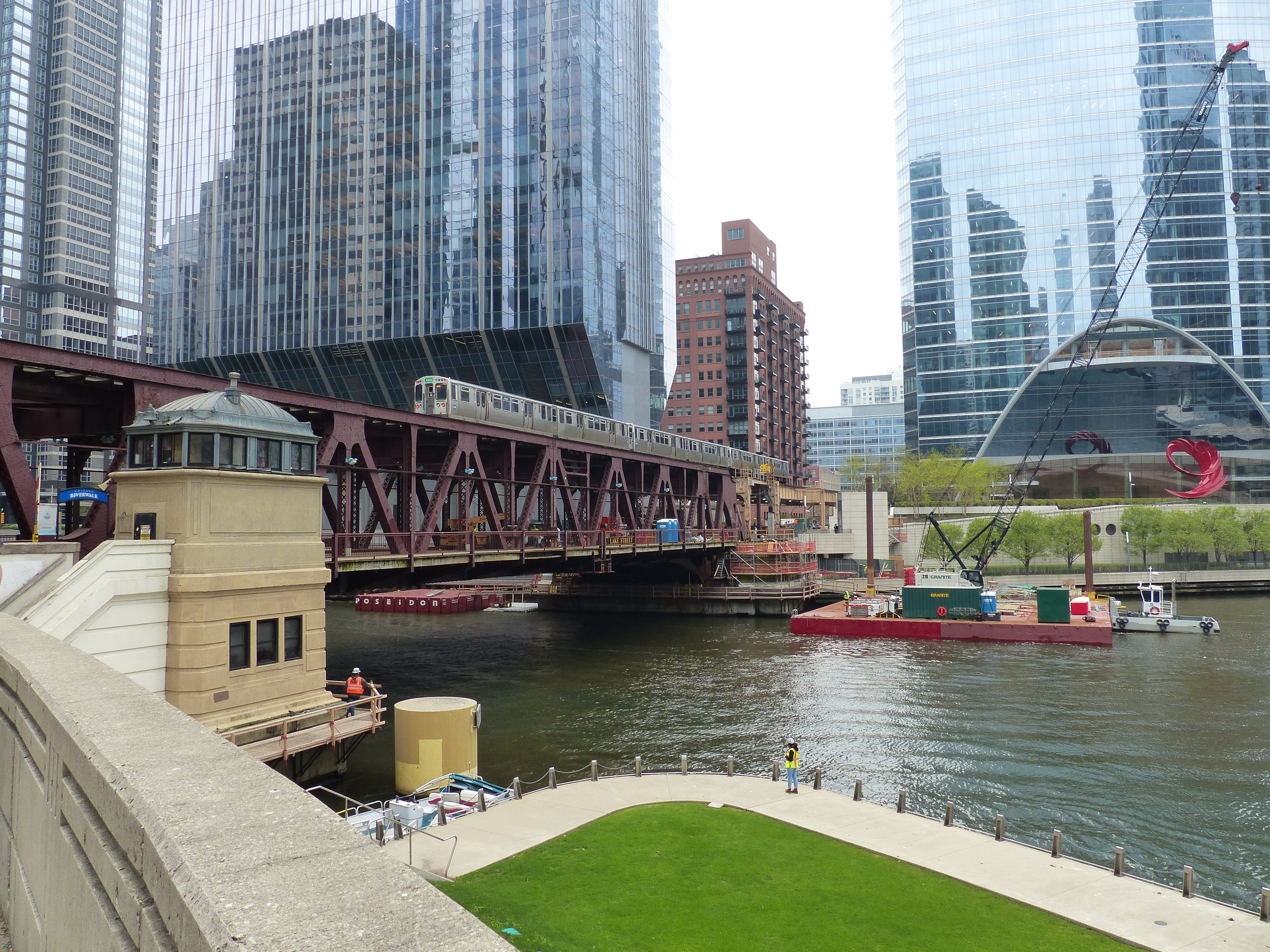
Photo 1 — Pre‑Lift Conditions
Time: 11:27 AM. Camera position: NE corner of Wacker & Lake, looking SW
Conditions: Cloudy, warm, high urban activity. Bridge status: Both leaves down; trains active on the upper deck
Operational & Structural Observations
- Construction presence: Crews and equipment staged on the west leaf, consistent with ongoing work on the west approach span and the north-side bridge house area.
- Scaffolding visible under the west leaf, likely tied to steel inspection, floor beam access, or counterweight‑pit work.
- Floating platforms/barges positioned on both sides of the west leaf abutment—typical for steel repair, rivet/bolt replacement, or underside inspection.
- River Point Park interface: crews active on the lower levels near the river edge.
- The geometry of the River Point retaining walls and walkways is clearly visible due to the low river traffic at this moment.
Transit context
- Pedestrian environment: High foot traffic along Wacker; no active bridge‑closure procedures initiated at this time.
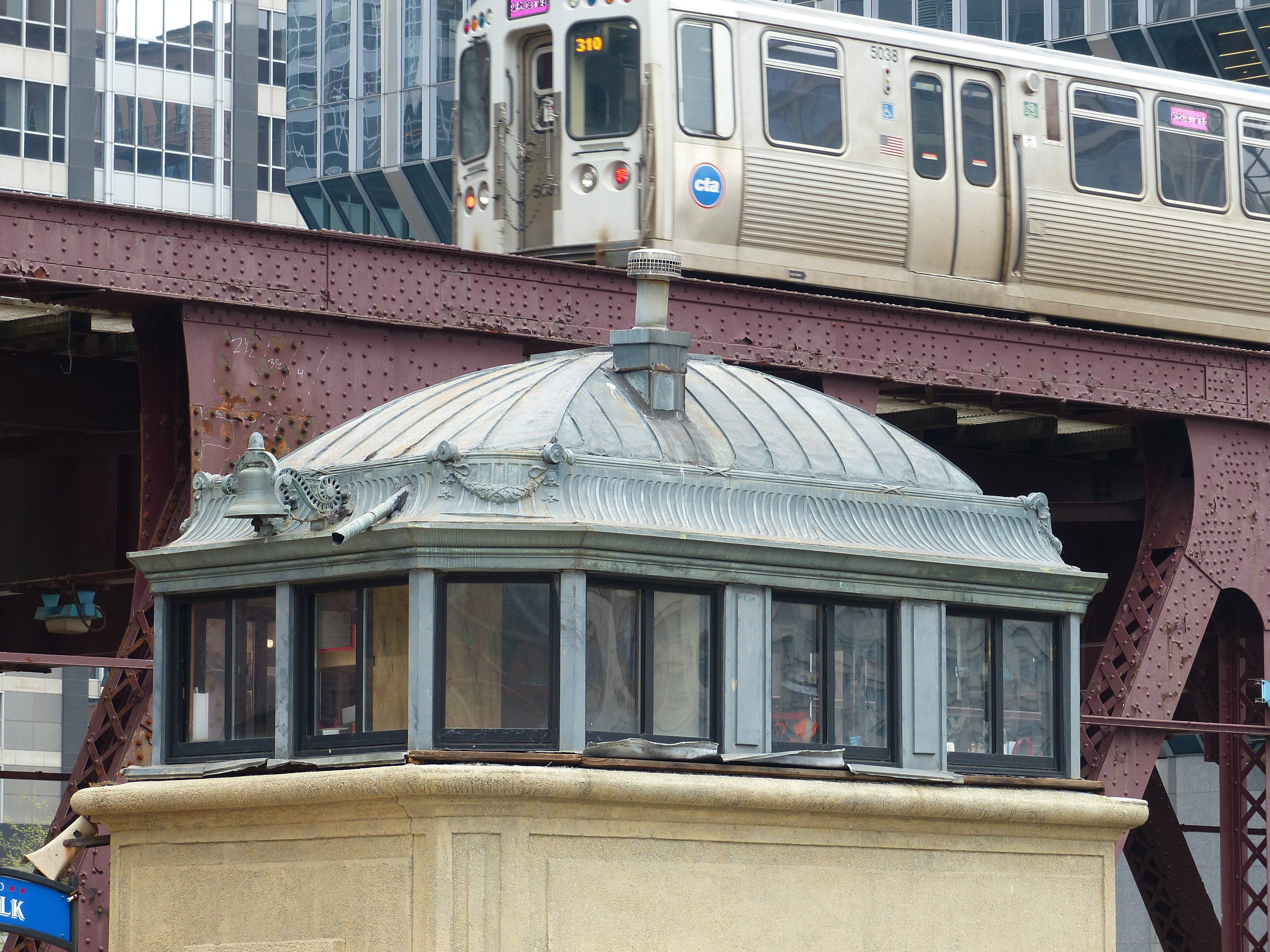
Photo 2 — NE Bridge house Crew
Time: 11:28 AM. Subject: Northeast bridge tender’s house with crew visible inside
Operational Observations
- Crew posture:
- Personnel inside the NE bridge house appear to be in pre‑lift monitoring mode—standing positions, window visibility, and attention directed toward the river and leaf mechanisms.
- This is consistent with the standard Chicago bascule protocol: visual confirmation of river traffic, pedestrian clearance, and coordination with the opposite house (though the NW house is absent this season).
- Train movement:
- The eastbound Pink Line train indicates that the CTA has not yet halted traffic for the lift. The timing (11:28) suggests the bridge crew is in the final pre‑lift checks.
Architectural/Structural Notes
- The telephoto view highlights the bridge house’s style: window patterns, roof curvature, and copper cladding, focusing on the east leaf and the relationship with the deck steelwork.
This frame is particularly valuable for documenting crew visibility zones and bridge house operational ergonomics.
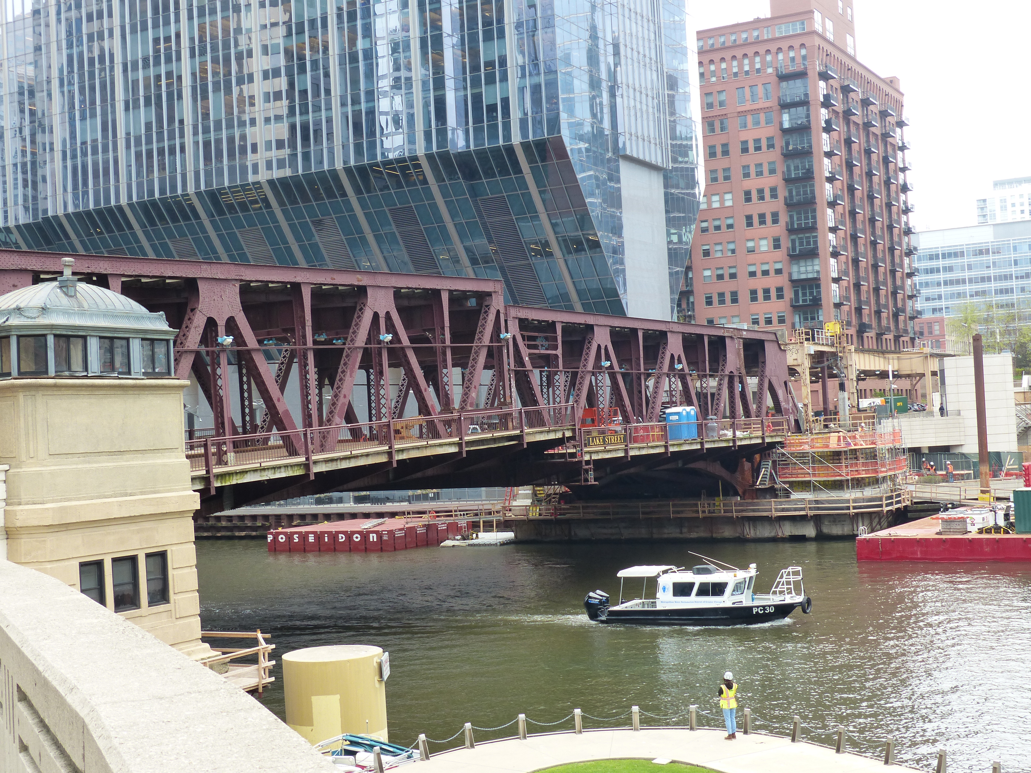
Photo 3 — Lift Initiation (East Leaf Only)
Time: 11:32 AM. Camera position: Same as Photo 1, slightly adjusted for angle
Key Observations
- East leaf movement:
- The lift works with the east leaf only, confirming asymmetric operation. The west leaf remains down due to construction staging and the absence of the northwest bridge house.
- Northwest bridge house removal:
- The west‑corner bridge tender’s house is dismantled, exposing:
- More of the River Point south‑edge retaining structures
- Additional visibility of the west leaf train‑deck approach span
- This is a significant change from your 2019–2023 documentation, where both houses were intact and symmetrically positioned.
- The west‑corner bridge tender’s house is dismantled, exposing:
- Construction footprint:
- The cleared area where the NW house once stood suggests active or upcoming structural work—possibly steel replacement, house‑drum restoration, or counterweight‑pit access. The floating equipment platforms remain positioned for underside access.
Synthesis for Engineering & Planning Use
What these frames show for the urban & transit context:
- Pedestrian traffic is beginning to slow as the lift sequence becomes visible.
- No train is present on the upper deck at this moment, consistent with CTA’s standard lift‑clearance window.
1. Early‑season operational asymmetry: Only the east leaf is lifting, likely due to west‑side construction constraints.
2. Bridge house architectural change: The dismantling of the NW bridge house is a major structural and historical development.
3. Multi‑layered construction environment: Simultaneous work is ongoing at west leaf underside, west approach span, River Point Park interface, and bridge house removal zone.
4. Transit‑bridge coordination: The sequence of train movement vs. crew posture vs. leaf initiation is clearly documented across the three timestamps.
The East Leaf Raised and Bridge Crew Positions
Photo 4 — West‑Leaf Deck Crews Observe the Lift
Time: 11:34 AM. Position: North side of Wacker Drive near Lake Street, looking southwest
Leaf Status: East leaf rising; west leaf fixed in the down position. Reason for placement: Prioritized first out of respect for the crews working on the exposed deck.
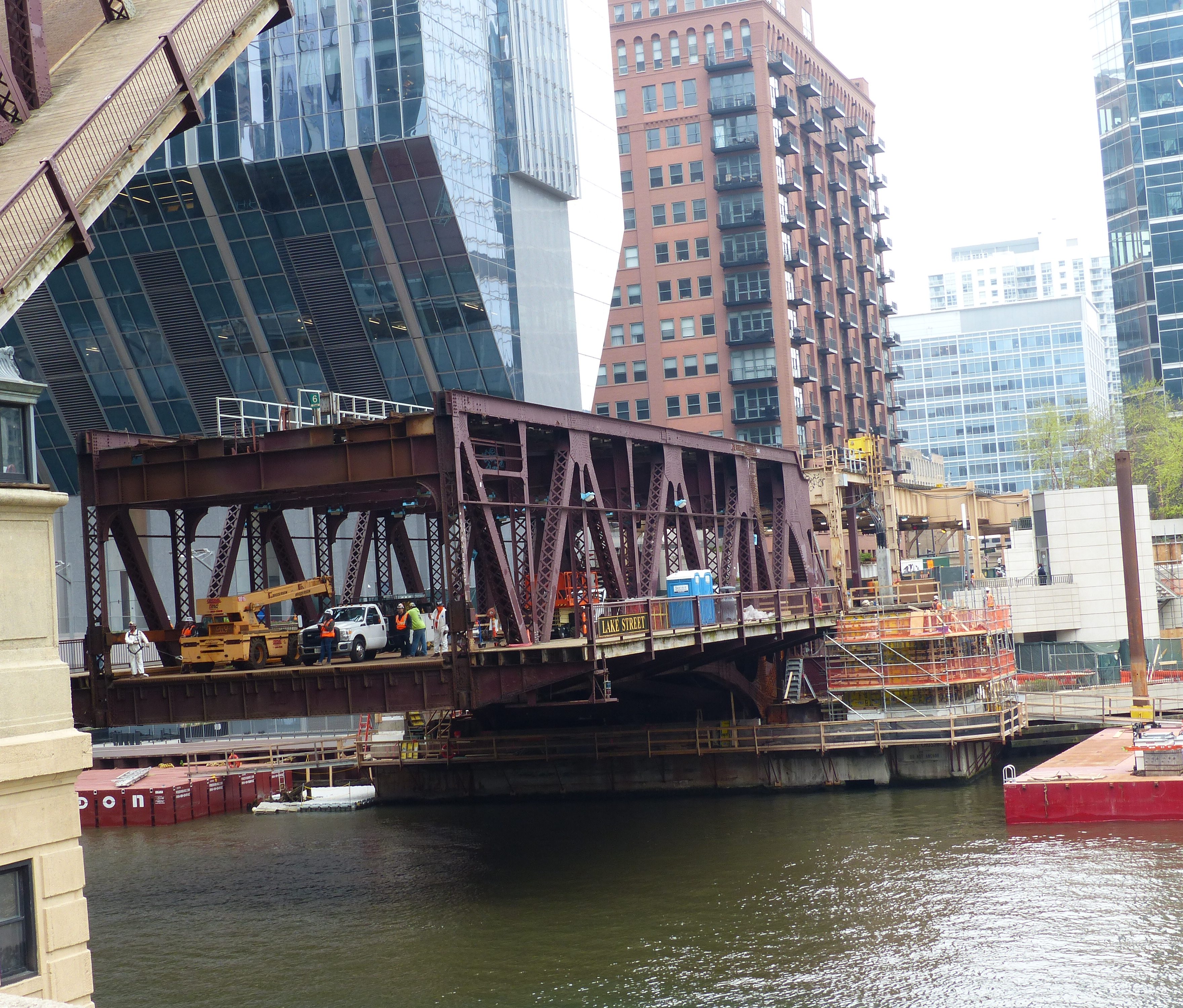
- Presence of vehicles, tools, and safety‑vested personnel confirms ongoing west‑leaf work, likely tied to underside steel inspection, approach‑span rehabilitation, or bridge house‑related structural access.
- The vantage point shows the deck plate, curb lines, and sidewalk cantilever brackets clearly, offering a rare unobstructed view of the west leaf’s surface during a lift event.
- The surrounding towers and River Point Park geometry frame the crews against the rising east leaf, emphasizing the scale of the operation and the complexity of working on an active movable bridge in a dense corridor.
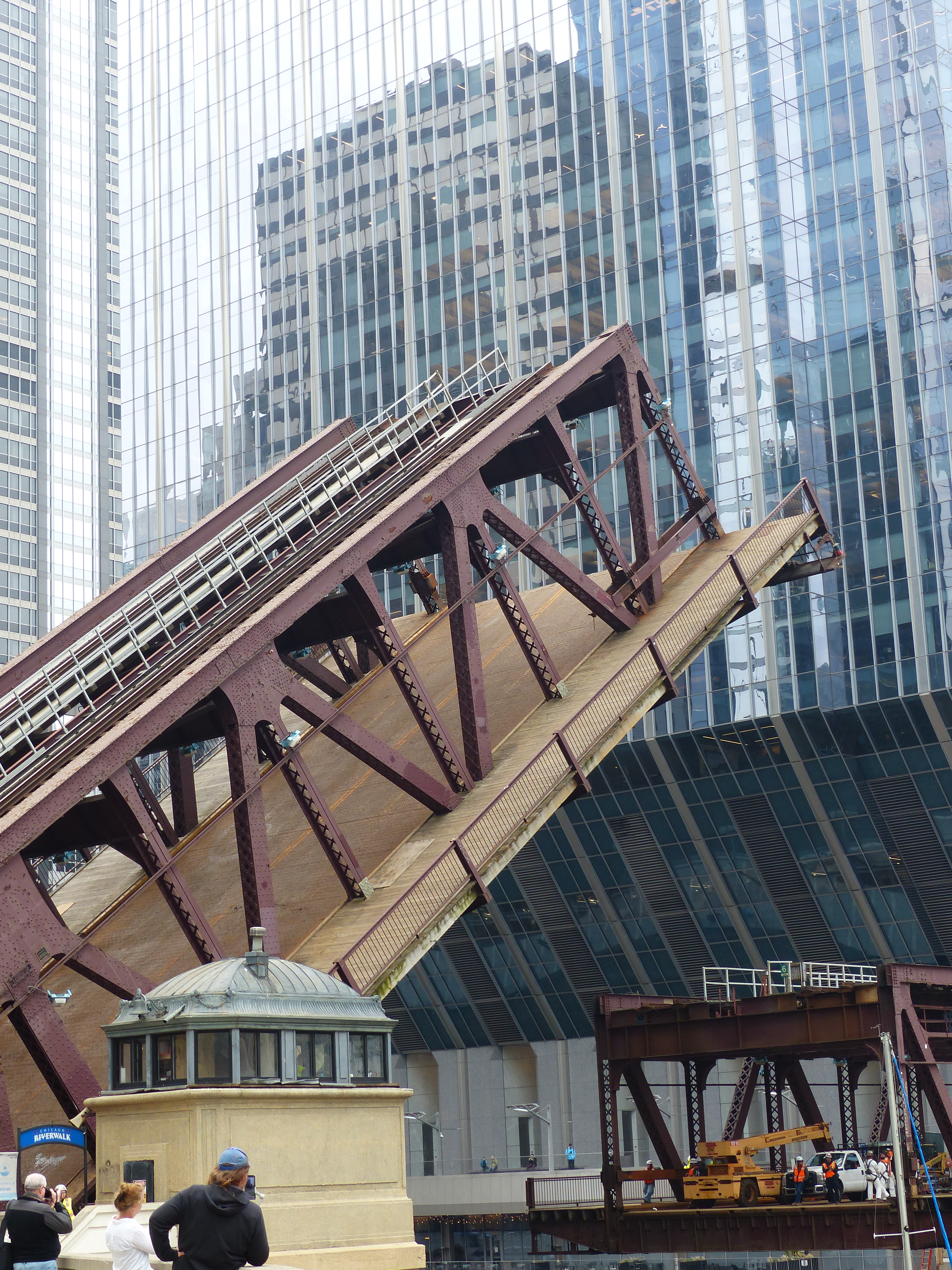
Photo 5 — East Leaf Near Maximum Angle
Time: 11:33 AM. Position: Same general vantage point, slight shift for angle. Structural Features Documented: This frame is unusually rich in structural detail, capturing elements that are often obscured when the leaf is down:
- Warren through‑truss geometry
- Diagonals and verticals clearly visible
- Intermediate bracing and X‑bracing patterns exposed
- Train deck
- Rail alignment, guard timbers, and lateral bracing visible
- Relationship between the train deck and the truss chords is well‑documented
- Center lock
- The east‑leaf center lock assembly is exposed at the leaf’s base, showing the mating surfaces and lock‑bar geometry
- Road deck and sidewalks
- Grating, curb lines, and sidewalk cantilevers visible in profile
River Traffic Interaction
- The mast of a sailboat is visible as it passes north of the bridge, heading toward the Franklin Street Bridge. This provides a useful timestamp for river‑traffic sequencing and confirms the lift’s purpose: early‑season sailboat migration upriver.
Public Observation
- Onlookers along the riverwalk and Wacker Drive are watching and recording the lift. Their presence underscores the public visibility of these operations and the educational value of your documentation.
- Documenting active construction‑crew engagement during a live lift
- Capturing rare structural exposures of the Warren truss, train deck, and center lock
- Showing river‑traffic coordination with a sailboat passing northbound
- Reinforcing the asymmetric lift condition (east leaf only) tied to west‑leaf construction and the removed northwest bridge house
- They also serve as a natural midpoint in the sequence—transitioning from pre‑lift and lift initiation to full‑height exposure and river‑traffic passage.
Franklin Street Bridge: Date: 1920. Style: Pratt Pony Truss. Chicago-style fixed trunnion bascule, single-deck, double-leaf. Carries: Franklin Street over the Main Branch of the Chicago River. Operational Role: Franklin Street functions as the eastern gateway to the Main Branch lift procession. Its geometry and mechanical behavior coordinate with Wells Street immediately upstream.
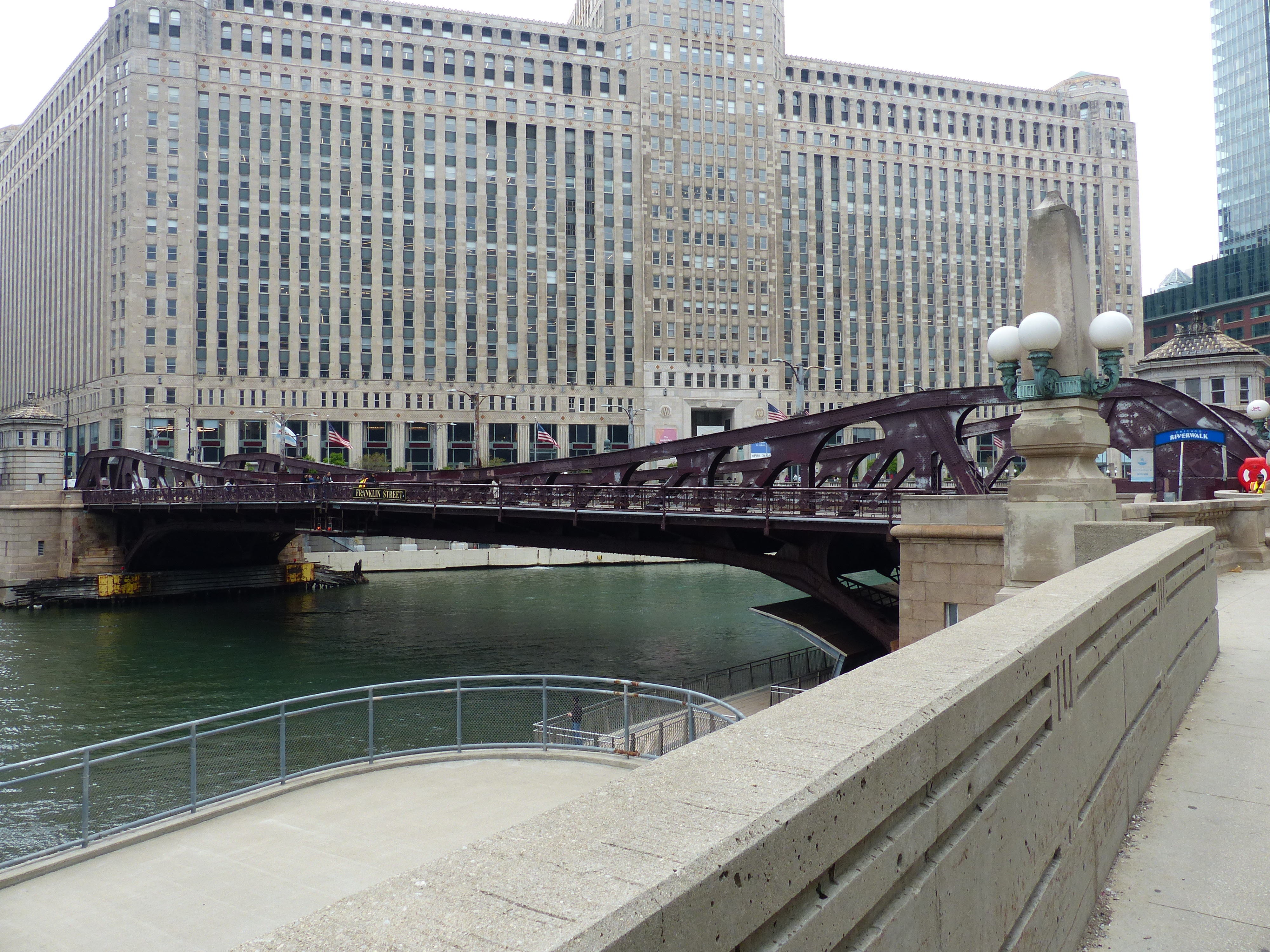
Photo 1 — Clear Span Before the Lift
Time: 11:38 AM. Location: Looking northeast from the Wacker Drive sidewalk
Interpretive note: Franklin’s pony truss form—lower than the through‑truss of Lake Street—keeps the visual weight at deck level, emphasizing the horizontal span and the relationship between the leaves and their abutments. This vantage point captures the bridge in its “resting geometry,” a baseline for the mechanical transformation that follows.
Photo 2 — Stop Lights Activated; Crews Prepare the Lift
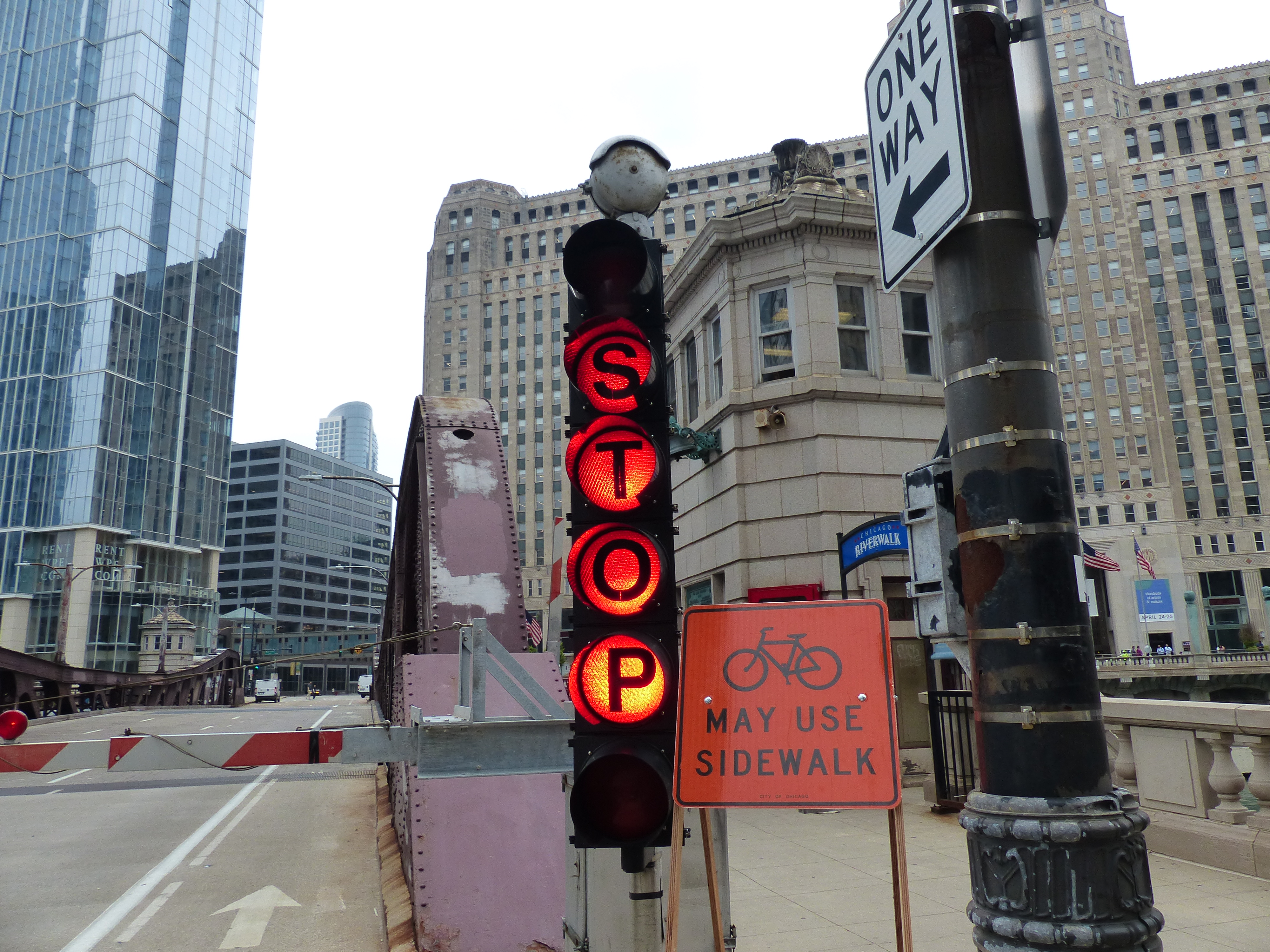
Time: 11:40 AM. Location: Looks north from the southwest corner of Wacker & Franklin. Surrounding buildings: The Mart, Wolf Point East, 350 N. Orleans.
Interpretive note: This is the operational threshold: the moment when the bridge transitions from urban roadway to navigational infrastructure. Activated signals, the audible bells, and the crew presence mark the shift from street traffic priority to river traffic priority.
Photo 3 — Both Leaves Rising
Time: 11:45 AM. Lens: 97mm (35mm equivalent), 17mm digital. View: Angled slightly northeast to center the bascule leaves
Interpretive note: At this angle, the bridge’s mechanical logic becomes legible: the truss panels articulate the load path, the gusset plates resolve the forces at each node, and the marine lights underscore the bridge’s dual identity as both roadway and navigational signal. The telephoto compression tightens the geometry, making the rising leaves feel monumental.
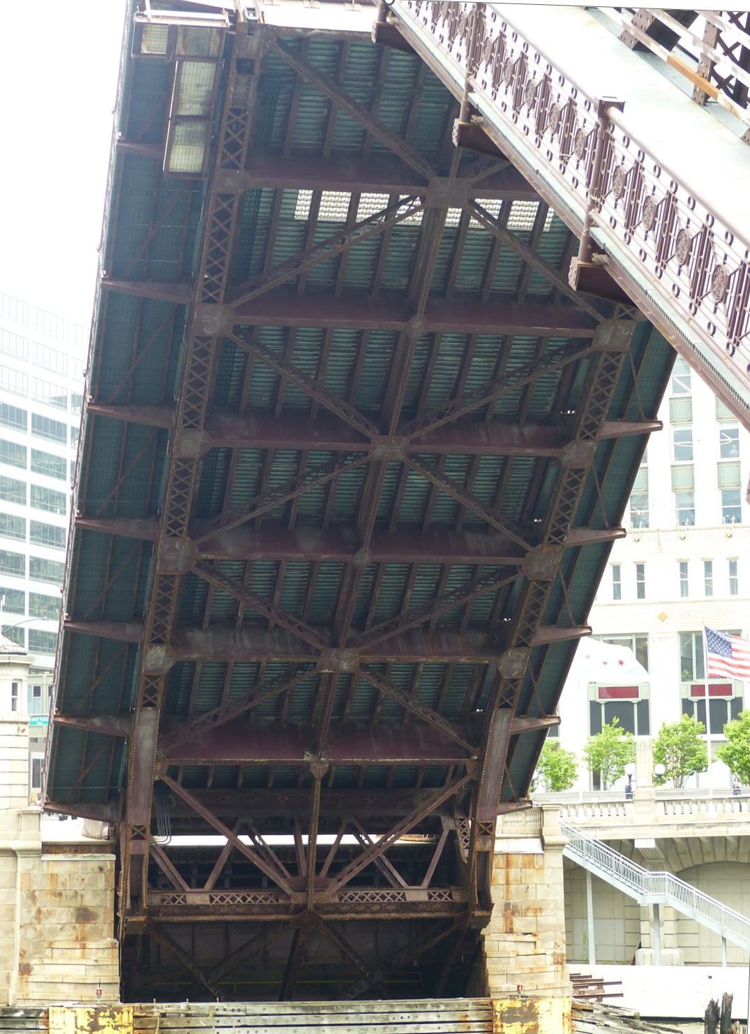
The underside of the north leaf dominates the composition, revealing the full hierarchy of the bascule’s substructure. From bottom to top: the counterweight pit, abutment and bridge bumpers, truss panel points where the leaf connects to the pit, additional panel points along the leaf itself, X‑bracing, stringers, floor beams, and the projecting sidewalk cantilevers. The photo isolates the mechanical anatomy of the bridge at the moment when its internal structure is most exposed.
Photo 4 — Substructure of the North Leaf
Time: 11:46 AM. View: Looking north. Post‑processing: Edited for lighting quality
Interpretive note: This is the bridge’s “cross‑section in motion.” The counterweight pit and panel points articulate the bascule’s rotational physics, while the stringers and floor beams show the roadway’s load‑bearing grid. Few vantage points offer this level of structural clarity, making this frame especially valuable for engineering documentation.
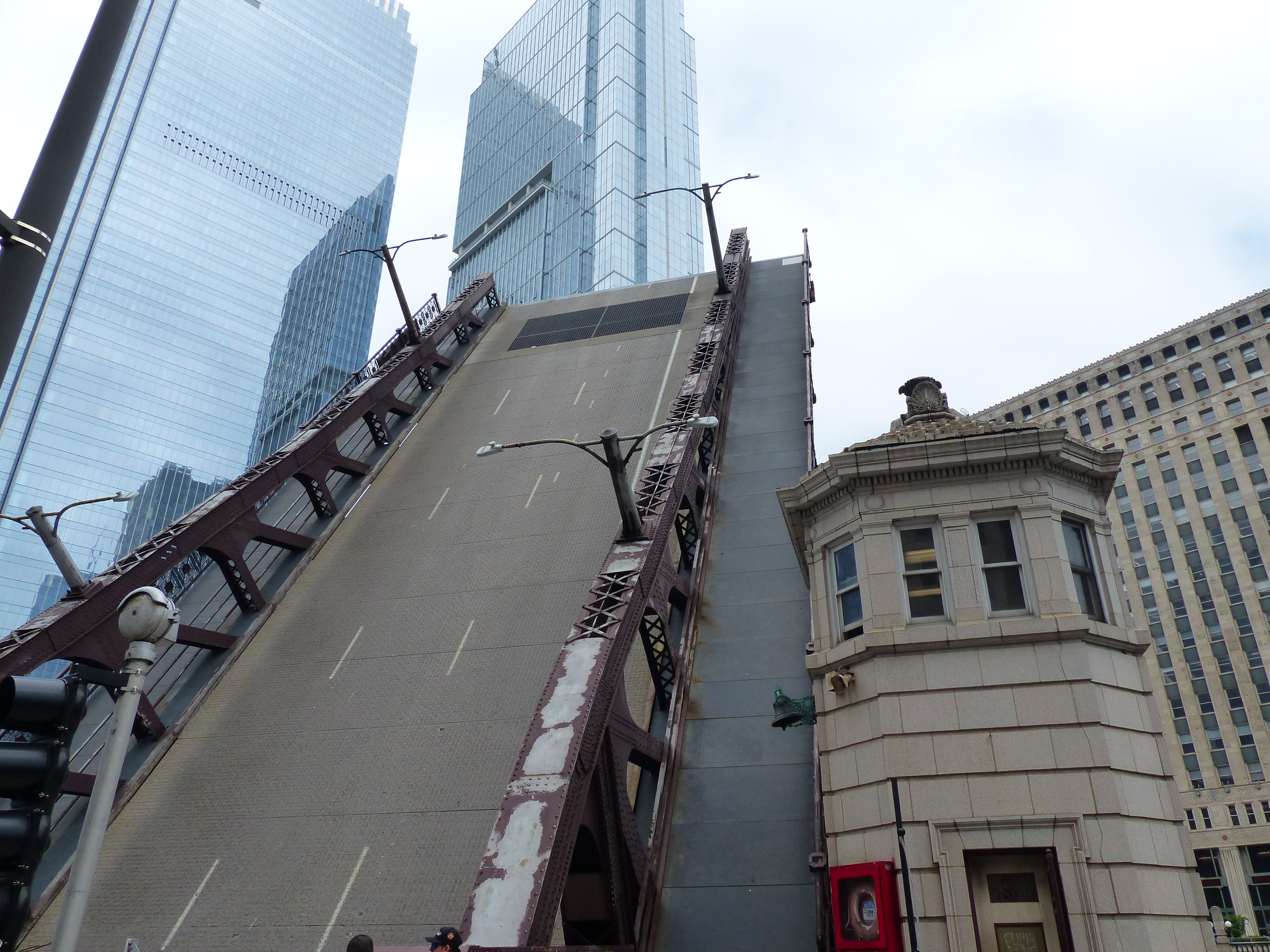
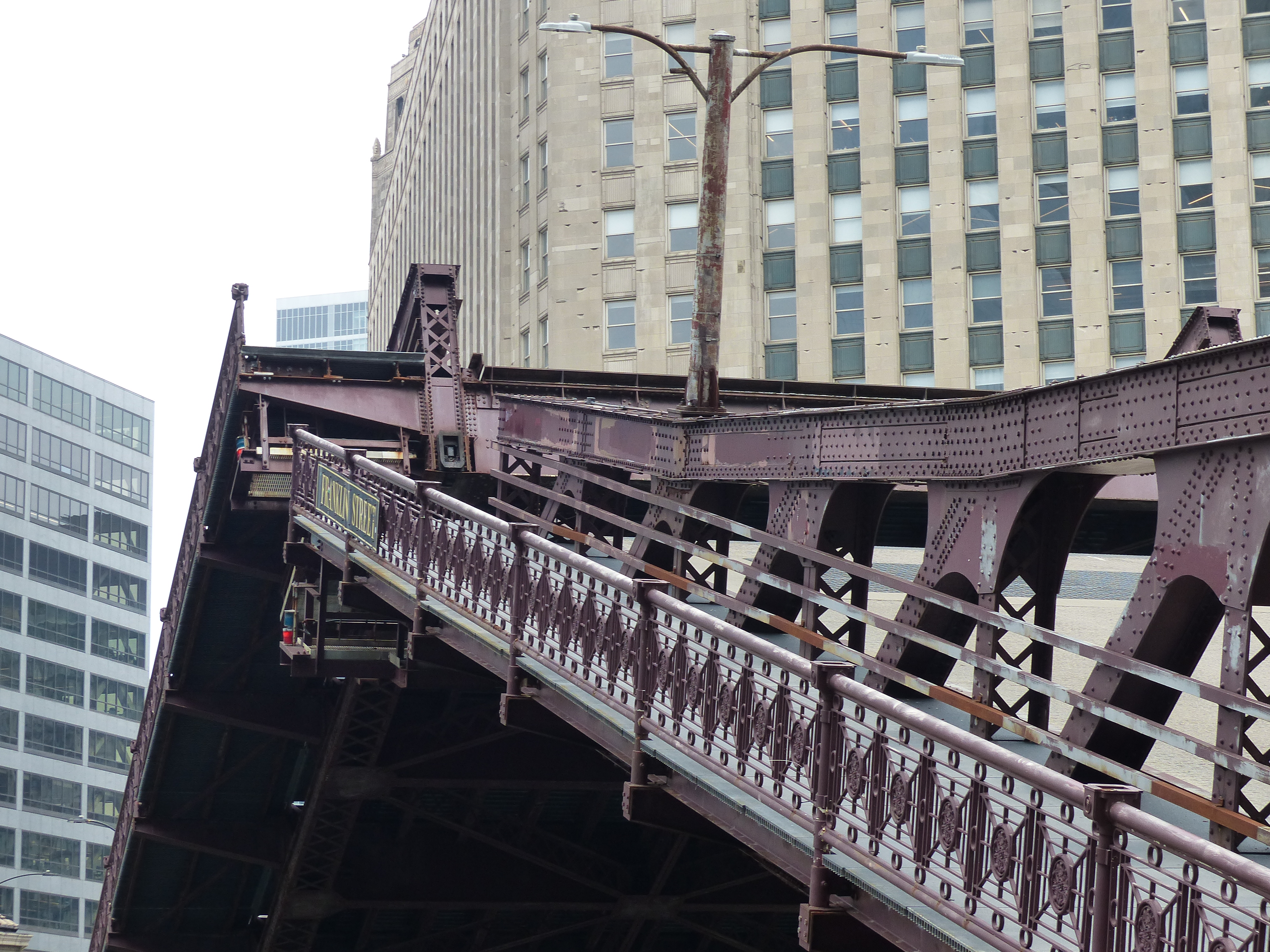
Photo 5. Raised South Leaf & Southeast Bridge Tender’s House Adjacency
Time: 11:47 AM. Photographer’s location: Southeast corner of N. Franklin Street and Wacker Drive. Surrounding buildings: The Mart, Wolf Point East, Salesforce Tower
Interpretive note: This frame captures the operational intimacy of a Chicago bascule bridge: the proximity of the tender’s house to the moving leaf, the visible signaling equipment, and the human presence implied by the lit interior. The structural vocabulary—X‑bracing, web members, and the weathered top chord—reinforces the bridge’s dual identity as both a working machine and a historic urban artifact.
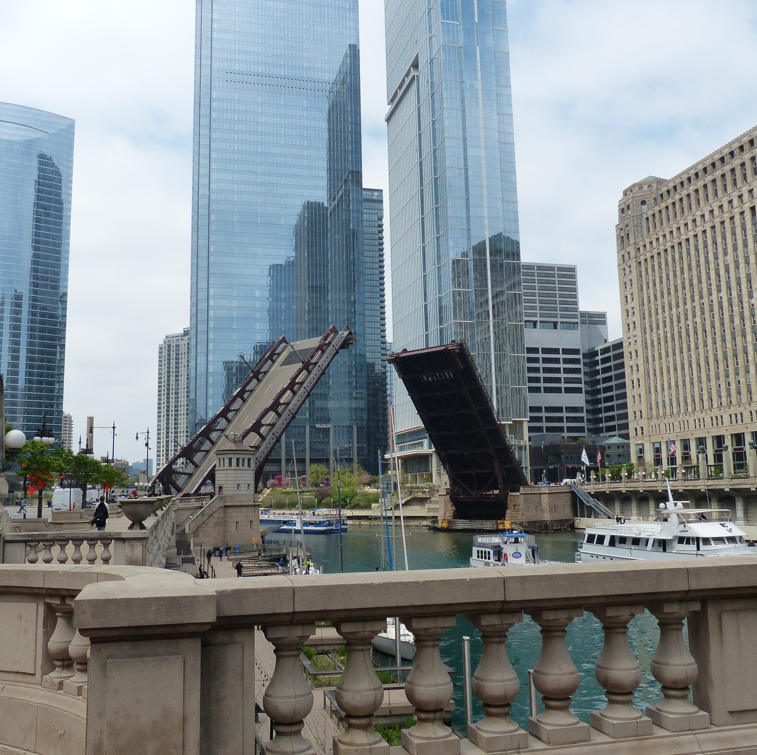
Photo 6: Both Leaves Fully Raised
Time: 11:51 AM. Location: Southwest corner of N. Wells Street and Wacker Drive
View direction: Looking west. Surrounding buildings (westward frame): The Mart (on the right), Salesforce Tower, Wolf Point East, River Point, 350 N. Orleans. River activity: Boats staging near the Wells Street Bridge for its upcoming lift
1. Leaf Geometry and Load Path
- Each leaf is a Pratt pony truss, meaning the diagonals are in tension and the verticals in compression during normal deck loading.
- When raised, the load path inverts: the truss panels near the trunnion carry the greatest moment as the leaf rotates upward.
- Gusset plates at each panel point resolve the shifting forces as the leaf transitions from horizontal roadway to near‑vertical lift position.
- The pony‑truss form keeps the structural depth low, preserving sightlines along Wacker Drive while still providing the stiffness needed for a 1900s‑era bascule.
2. Trunnions, Counterweights, and Rotation
- The trunnions act as the rotational axis, transferring the leaf’s weight into the counterweight pit.
- The counterweights—hidden below deck level—balance the mass of the leaf so the motors only overcome friction and wind load, not the full weight of the span.
- The panel points nearest the trunnion show the densest concentration of rivets and gusseting, reflecting the high bending stresses during rotation.
- Franklin’s counterweight geometry is compact compared to Lake Street’s through‑truss system, giving it a faster, cleaner lift cycle.
Interpretive note: This westward perspective emphasizes Franklin’s role as the eastern gateway to the Main Branch lift procession. The raised leaves create a momentary architectural aperture, while the boats assembling downstream signal the continuous choreography of spring river traffic. The bridge sits at a critical bend in the Main Branch, where the river’s geometry and the canyon of towers create a natural stage for lift operations. Boats staging near Wells Street during your 11:51 AM frame illustrate the sequential choreography of Main Branch lift days.
Structural Logic Sidebar — Franklin Street Bridge. Main Branch • Chicago River • Bascule Mechanics in Context.
1. Substructure Exposure During Lift
When the leaves rise, the underside reveals the full structural hierarchy including the counterweight pit, abutment and bridge bumpers, truss panel points (connection to pit + leaf proper), and X‑bracing in the truss web. The views also expose stringers running longitudinally, floor beams tying the leaf laterally, and sidewalk cantilevers projecting outward. This “cross‑section in motion” is only visible during a lift, making it one of the most instructive bascule views on the Main Branch.
2. Mechanical and Navigational Systems
- Center lock mechanisms secure the leaves together when closed.
- Marine lights mounted beneath the deck signal river traffic during lifts.
- Street lighting and sidewalk railings are integrated into the truss chords, a hallmark of Chicago’s early‑20th‑century bascule design.
- Bridge tender’s houses (southeast and northwest) contain the controls, bells, and communication systems. The southeast house is especially prominent, with its bell and life‑saving ring visible.
3. Why the Leaf–Counterweight Interface Endures Extremely High Stresses
1. The trunnion region carries the entire bending moment of the rotating leaf
When a bascule leaf rises, its weight shifts from being supported along its length (stringers → floor beams → truss → abutments) to being supported almost entirely at one point: the trunnion. This creates a massive cantilever moment at the trunnion panel points. This means that the leaf’s center of gravity is several meters away from the trunnion. That distance acts as a moment arm. The bending moment ( M = W \times d ) becomes enormous.
Even though the counterweight balances the leaf, the structural members at the trunnion still experience huge internal forces because they must transmit the leaf’s dead load. dynamic loads from wind. inertia from starting/stopping rotation, and the counterweight’s opposing torque. This is why the gusset plates near the trunnion are the thickest and most heavily riveted on the entire bridge.
2. The counterweight and leaf are connected through a rigid truss “hinge zone”
The leaf and counterweight are not separate pieces — they are two ends of a single rotating structure. Between them is a short but extremely stiff truss segment that must:
- transfer the counterweight’s torque into the leaf
- resist shear as the leaf rotates
- maintain alignment of the trunnion bearings
- prevent distortion of the pony truss geometry
This hinge zone is where panel points are densest, gusset plates are largest, rivets are most numerous, and bracing is most redundant. It is the structural “neck” of the bascule — compact, rigid, and highly stressed.
3. The counterweight produces its own massive forces. The counterweight is designed to nearly balance the leaf, but “nearly” is the key word.
It is intentionally slightly heavier so the motors only need to overcome friction, wind load, and inertia. But that slight imbalance still produces large compressive and tensile forces in the hinge zone.
Additionally, the counterweight is extremely dense (concrete + steel punchings). Its center of gravity is far behind the trunnion. It produces a large opposing moment that must be transmitted through the same panel points that carry the leaf’s moment.
Thus, the hinge zone is simultaneously resisting the leaf’s torque, the counterweight’s torque, and the dynamic effects of rotation. This is why the stresses are highest here.
4. During rotation, the load path changes continuously
As the leaf rises the center of gravity shifts, the moment arm changes, the distribution of tension and compression in the truss reverses, the counterweight’s effective torque increases as its geometry rotates. This means the hinge zone must handle peak stresses at the start of the lift (overcoming static friction), changing stresses mid‑rotation, and impact and settling forces when the leaf returns to the rest position. It is the only part of the bridge that experiences every load case in every lift.
5. The photos show the panel points nearest the trunnion, the X‑bracing that stiffens the hinge zone, the floor beams and stringers transitioning into the counterweight pit, and massive gusset plates that resolve the forces. This is the structural “engine room” of the bascule.
Conclusion
The mechanics of Chicago’s bascule bridges are displayed during the bridge lifts that occur every spring. These allow tall-mast craft to pass through the narrow clearances owing to the topography of the river.
Learning the technology of this amazing collection of bridges makes watching the lifts a fun and challenging experience. With the help of bridge crews as well as AI research, we learn about the stresses the parts of each bridge endure during the time the leaves are raised and lowered. Stresses are highest between the leaf and the counterweight because this hinge zone must transmit the full bending moment of the leaf, the opposing torque of the counterweight, and all dynamic loads of rotation through a compact, rigid, heavily reinforced truss segment.
The structural logic of our bridges is inseparable from the urban logic: the bridges are both a machine and a hinge point in the river’s architectural corridor. Bascule bridge mechanical systems are compact but highly legible, making them ideal teaching examples for how Chicago bascules communicate with both street and river users.
Resources
- Microsoft Copilot. “Technical Notes on the Structural Logic and Lift Sequence of the Lake Street Bridge.” Chicago River Bridge Documentation, 24 Apr. 2026.
AI-generated explanatory text. - Microsoft Copilot. “Technical Notes on the 22 April 2026 Lift Sequence of the Franklin Street Bridge.” Chicago River Bridge Documentation, 24 Apr. 2026. AI-generated explanatory text.
- Microsoft Copilot. “Technical Notes on the 22 April 2026 Lift Sequence of the Franklin Street Bridge.” Chicago River Bridge Documentation, 24 Apr. 2026. AI-generated explanatory text.
- Microsoft Copilot. “Structural Logic Sidebar: Franklin Street Bridge (Main Branch).” Chicago River Bridge Documentation, 24 Apr. 2026. AI-generated explanatory text.
