

Article and photographs by Divi Logan. Assisted by Copilot Smart AI.
I am pleased to share my photographic collection with bridge restoration companies, bridge crews, Chicago transportation departments, steel fabrication companies, and fans of bascule bridges.
I. About Lake Street Bridge
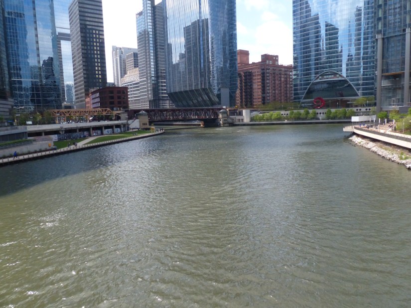
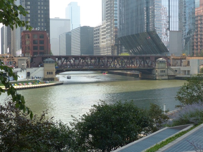
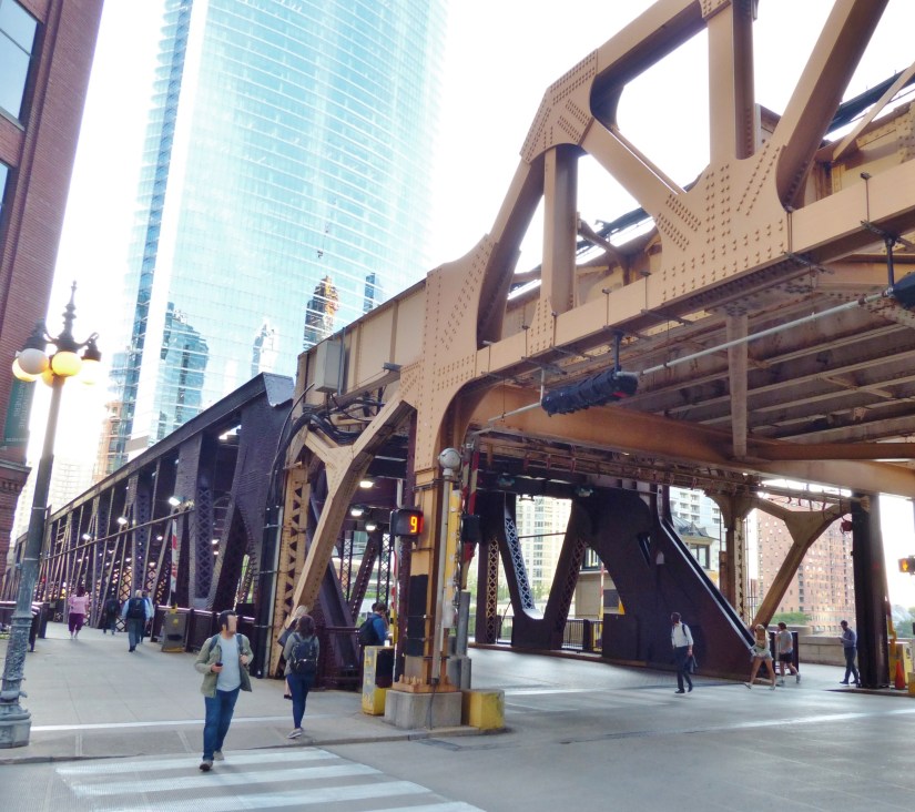
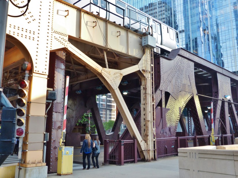
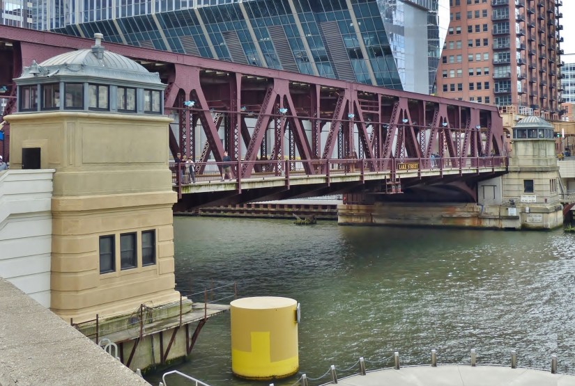
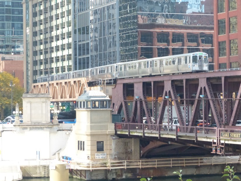
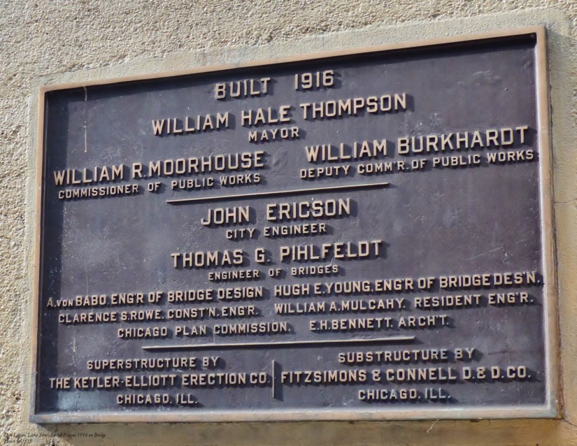
Lake Street Bridge is a double-leaf, double-deck bascule bridge, that carries commuter trains on its upper deck and vehicles and pedestrians on its lower deck. Completed in 1916, the bridge is now undergoing major maintenance.
Features of the bridge are shown in photographs taken between 2019 and 2025. A kid-friendly glossary is included to help our engineers of the future learn and appreciate the importance of bridges in our national infrastructure.

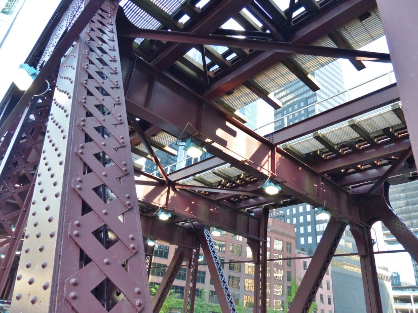
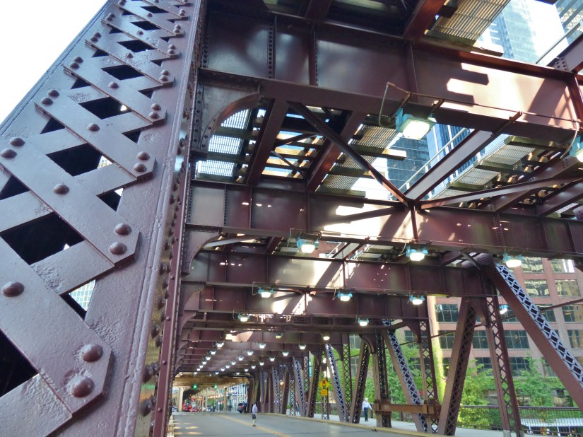
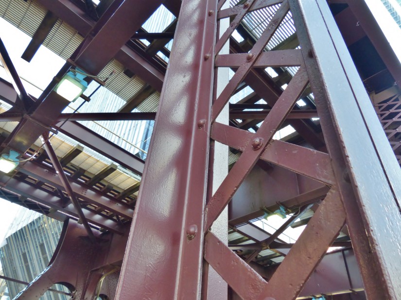
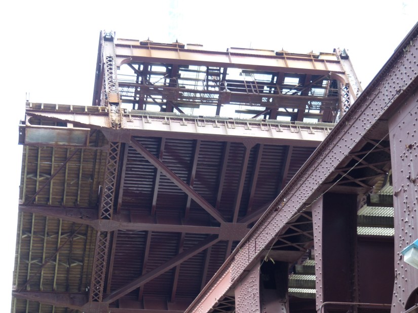
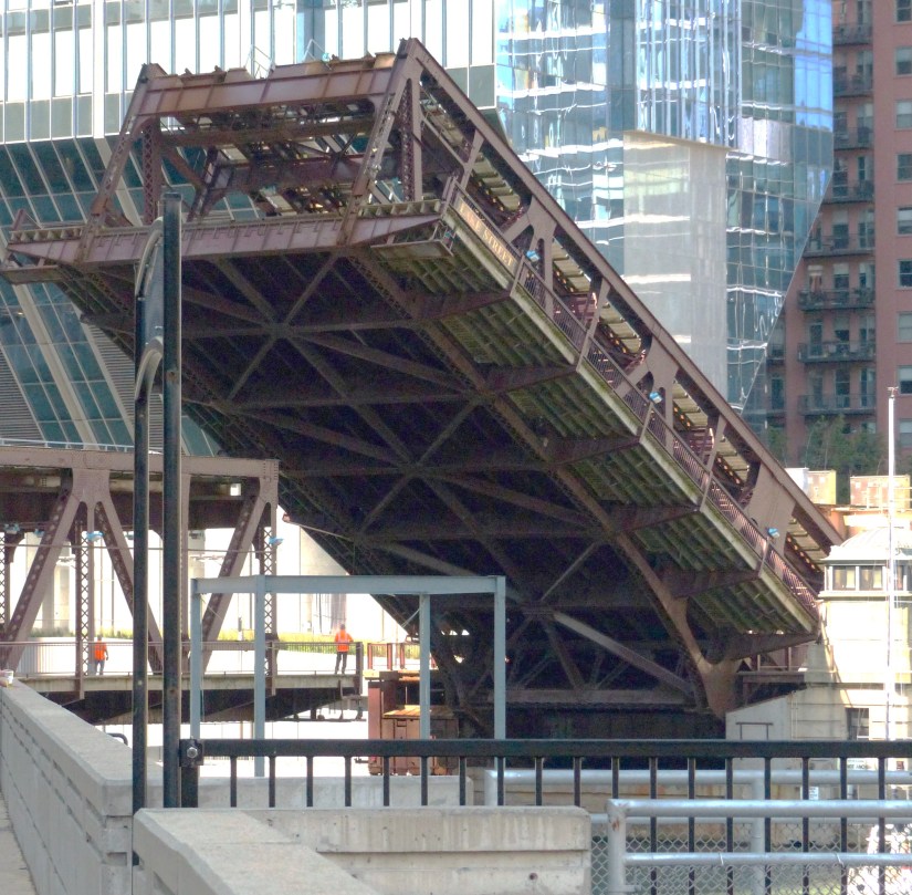
II. The Bridge’s Superstructure
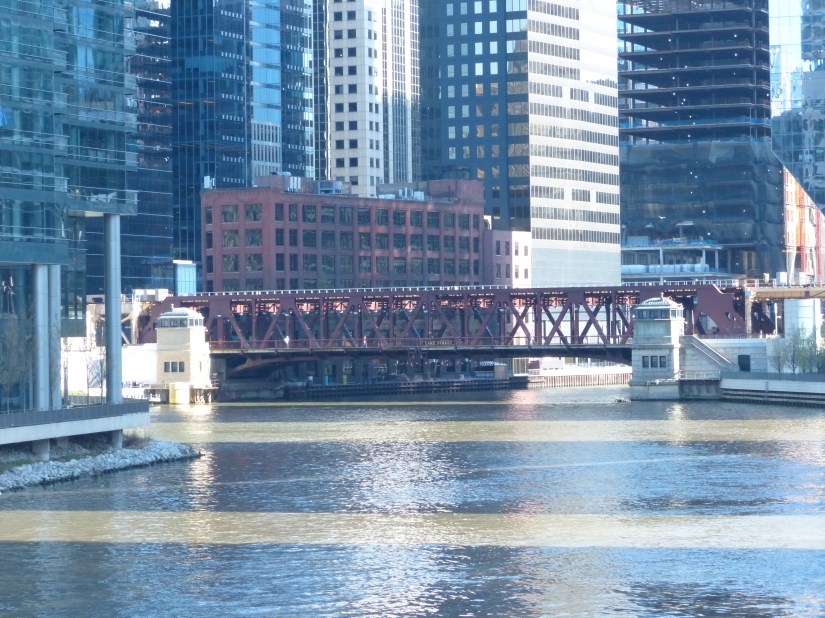
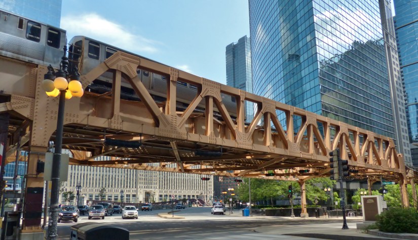
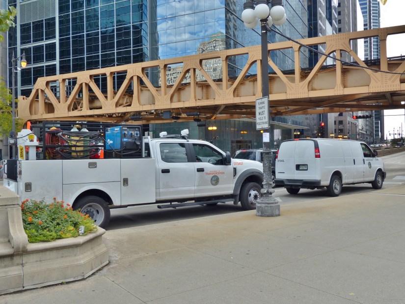
III. The Train Deck and Superstructure
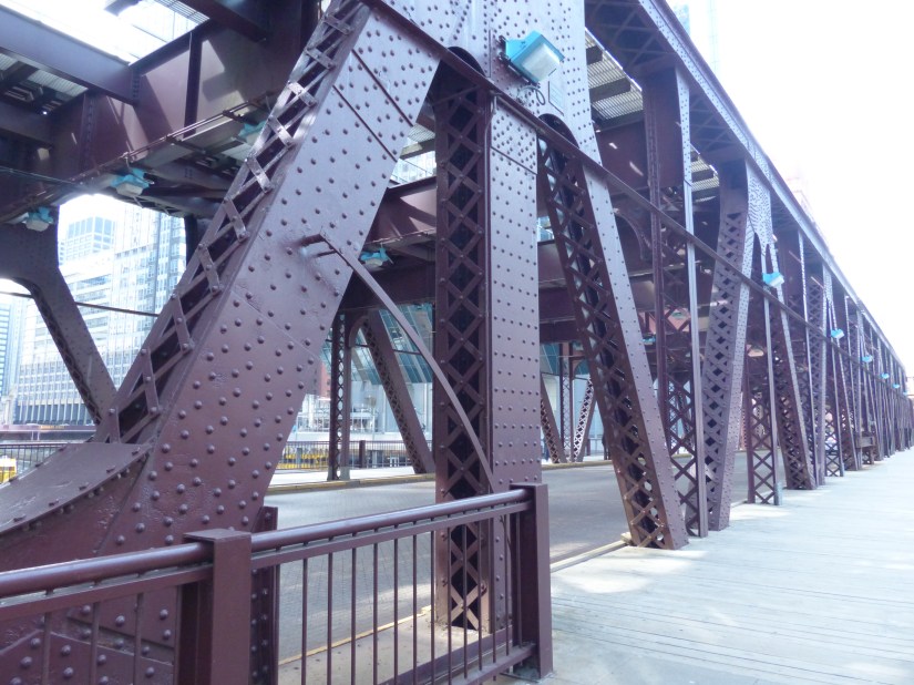
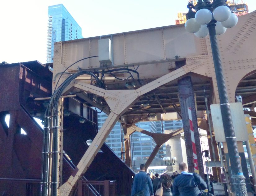
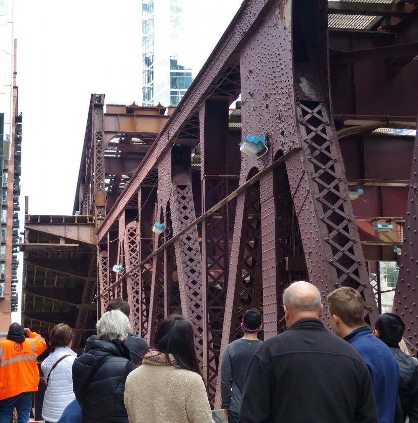
🔧 What X‑Bracing Does on a Bascule Bridge
1. Controls Lateral Sway and Racking
X‑bracing is the bridge’s way of saying: “I will not twist, I will not rack, even when the leaf is moving or when a train is pounding across the approach span.”
- Bascule leaves experience asymmetric loading during opening and closing.
- Wind loads hit the superstructure from the side, especially on Chicago’s river corridor.
- X‑bracing triangulates the frame so that lateral forces are redirected into tension in one diagonal and compression in the other, depending on load direction.
2. Stiffens the Truss During Leaf Rotation
Unlike a fixed truss bridge, a bascule leaf is a moving truss.
During rotation:
- The truss wants to deform out of plane.
- The counterweight pit and heel trunnion impose concentrated forces.
- The live load path changes as the leaf transitions from horizontal to partially lifted.
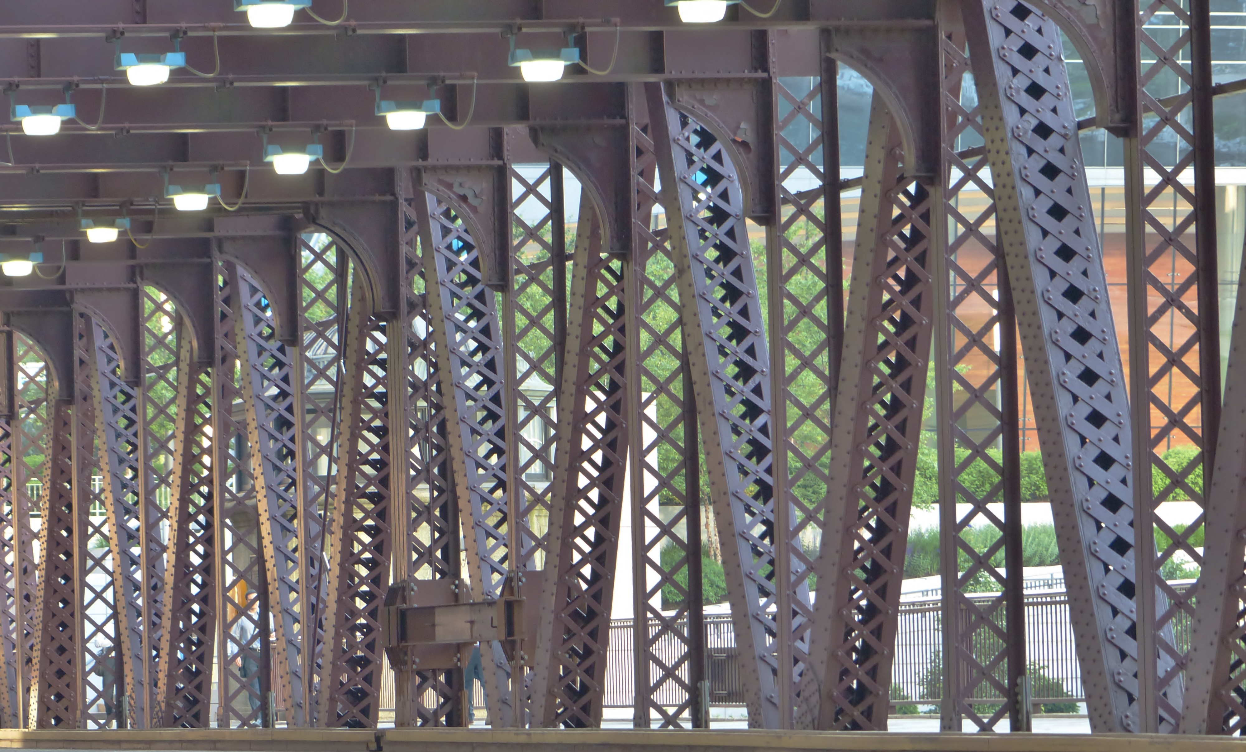
Sidebar. Kid‑Friendly Bridge Glossary: X‑Brace • Portal Frame • Lateral Bracing
X‑Brace
What it is:
Two long metal bars that cross each other to make the shape of an “X.”
Why it matters:
An X‑brace helps a bridge stay strong when the wind pushes on it or when trains and cars make it shake.
The “X” shape keeps the bridge from wobbling sideways, the same way crossing your arms makes your body steadier.
How to picture it:
Imagine two friends holding hands and leaning in opposite directions. Because they’re connected, they don’t fall over. That’s what the X‑brace does for the bridge.
Portal Frame
What it is:
A big, strong doorway made of steel beams at the entrance to a bridge.
Why it matters:
The portal frame helps the bridge stand tall and keeps the opening from bending or tilting. It’s especially important on bascule bridges, where the moving leaf needs a sturdy “doorway” to connect to.
How to picture it:
Think of the frame around your front door. It keeps the doorway square so the door can open and close smoothly. A portal frame does the same thing for a bridge.
Lateral Bracing
What it is:
A set of beams that run side‑to‑side under or inside a bridge.
Why it matters:
Lateral bracing keeps the bridge from sliding or swaying sideways.
It helps the whole structure act like one strong piece instead of lots of separate parts.
How to picture it:
If you’ve ever built a block tower and put your hands on both sides to keep it from tipping, you’ve acted like lateral bracing.
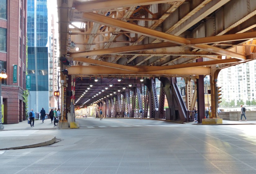
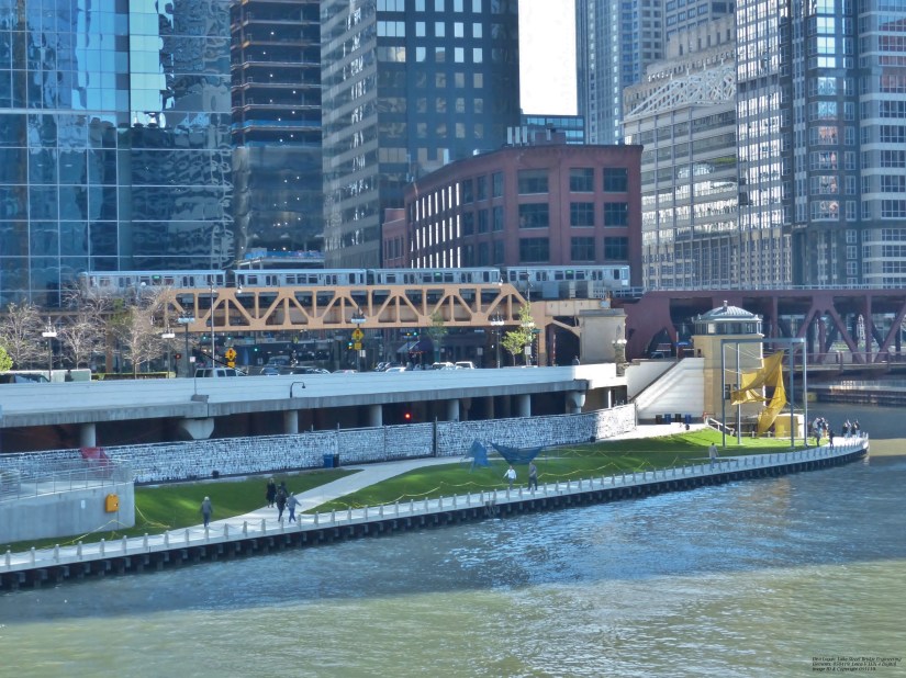
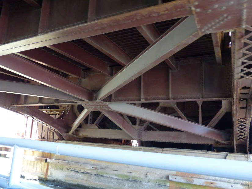
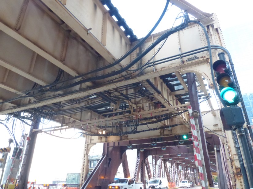
Purpose of the Lateral Braces Under the Train Deck Approach Span
(Lake Street Bridge — Lake–Wells Loop Junction)
1. Resisting Side‑to‑Side Forces from Train Movement
Trains entering and exiting the Lake–Wells Loop Junction generate powerful sideways forces when they brake, accelerate, and negotiate curves. The lateral braces tie the longitudinal girders together so the entire deck acts as one stiff, unified structure rather than a collection of independent beams.
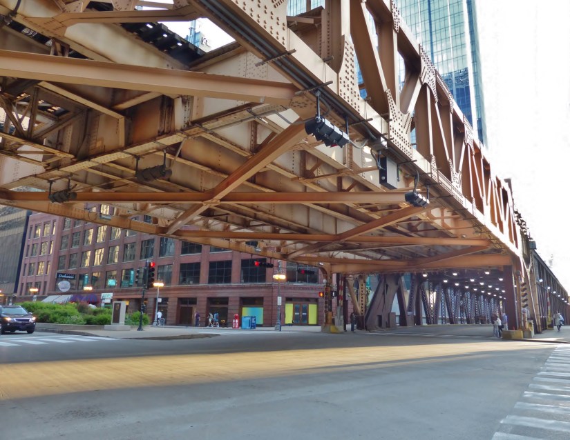
2. Preventing Racking, Twisting, and Sway
Without these braces, the approach span would be vulnerable to racking (parallelogram distortion), torsion, and lateral sway. The triangulated bracing system locks the geometry in place, keeping the deck square and stable even under heavy vibration.
3. Transferring Loads into the Portal Frame and Main Truss
The lateral braces channel side forces into the portal knee braces and the Warren through‑truss of the movable leaf. This clean load transfer prevents stress from accumulating in the deck and ensures the fixed span and movable span work together as a coordinated system.
4. Stabilizing the Transition Between Fixed Span and Movable Leaf
Because the bascule leaf rotates and changes stiffness during operation, the fixed approach span must remain absolutely steady. The lateral bracing provides the rigidity needed for the moving machinery to operate safely and predictably.
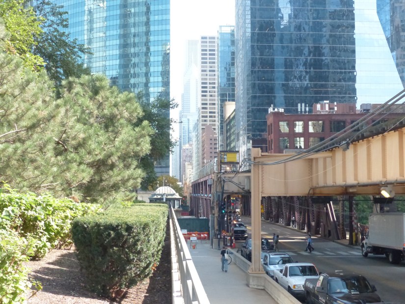
5. Supporting the Structure in a Dense Urban Environment
The Lake Street corridor experiences wind tunnel effects, heavy pedestrian and vehicle traffic, and constant urban vibration. The lateral bracing absorbs and redistributes these forces, protecting the structure from fatigue and long‑term deformation.
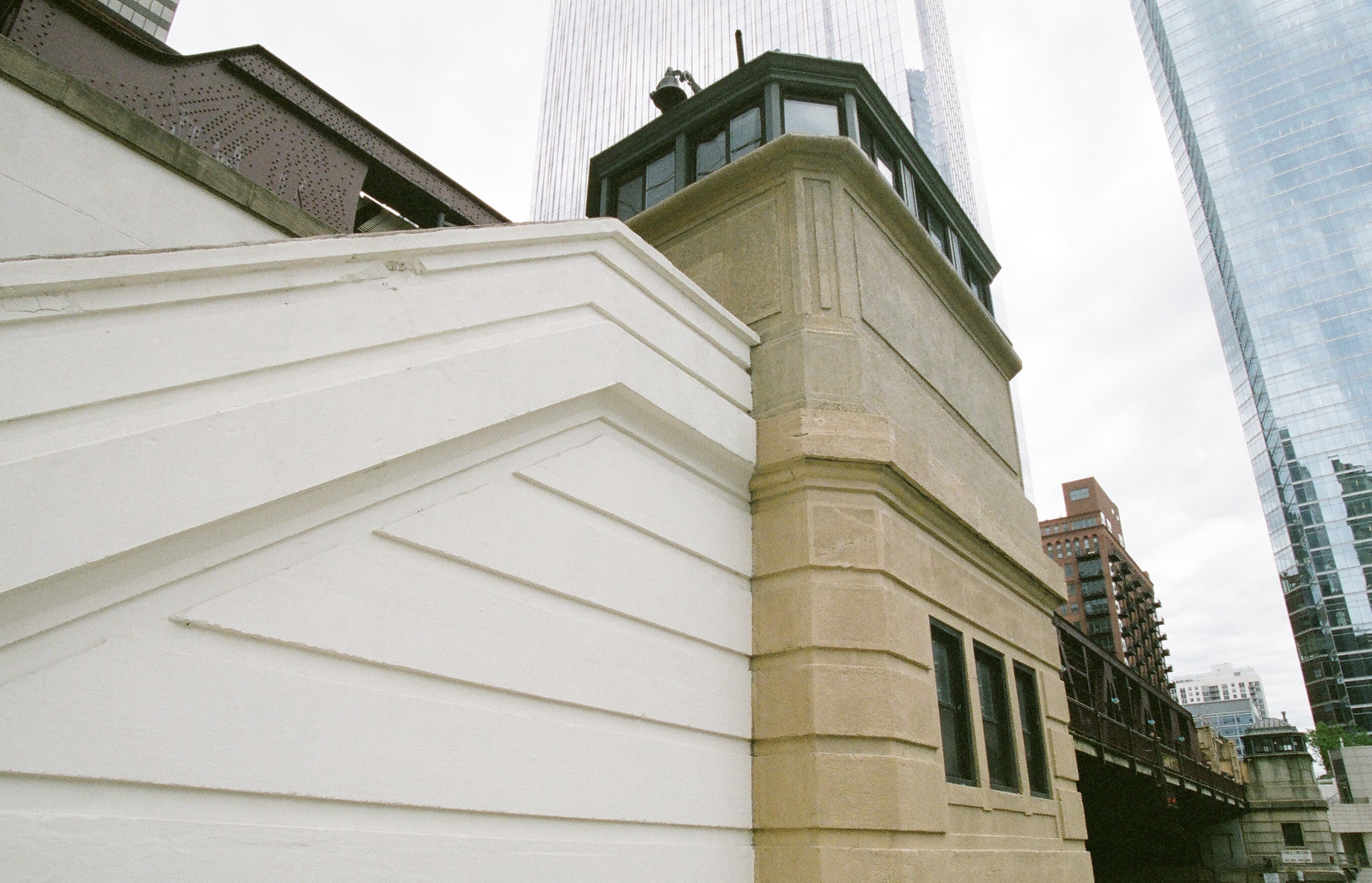
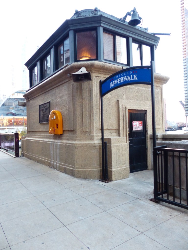
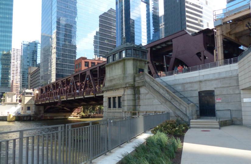
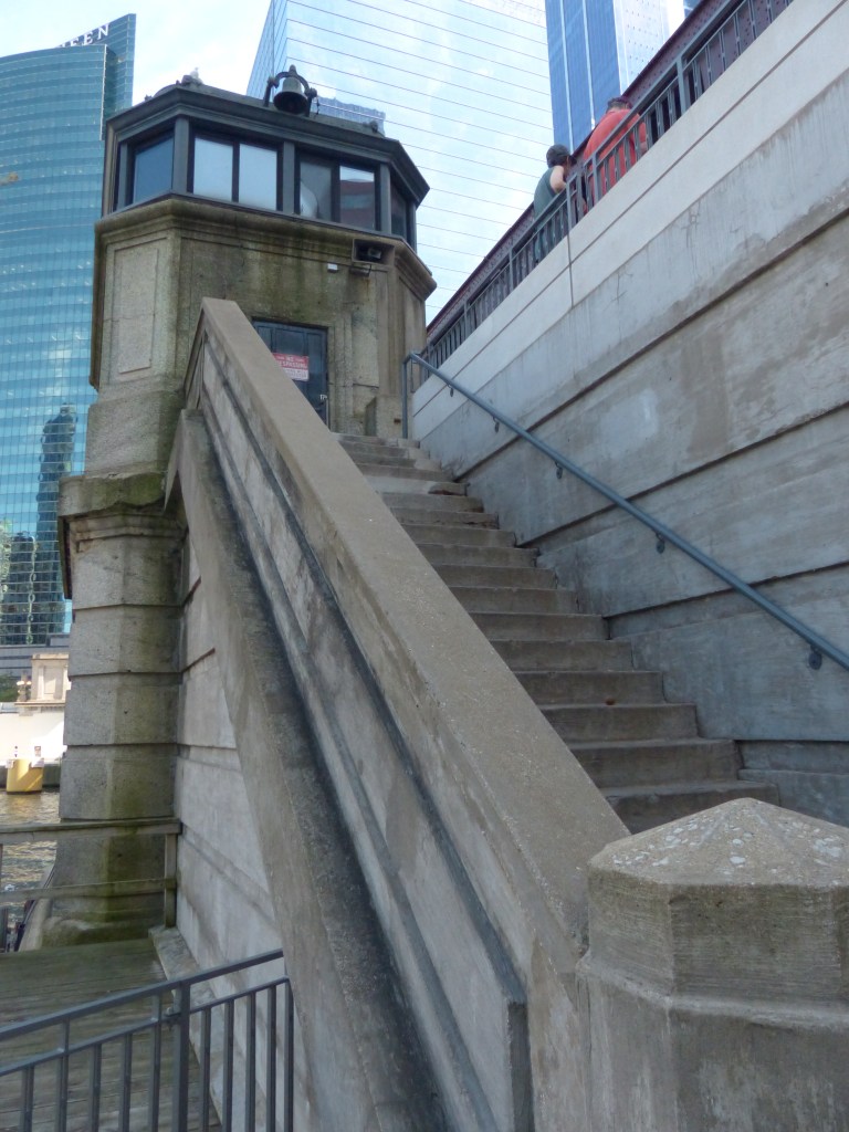
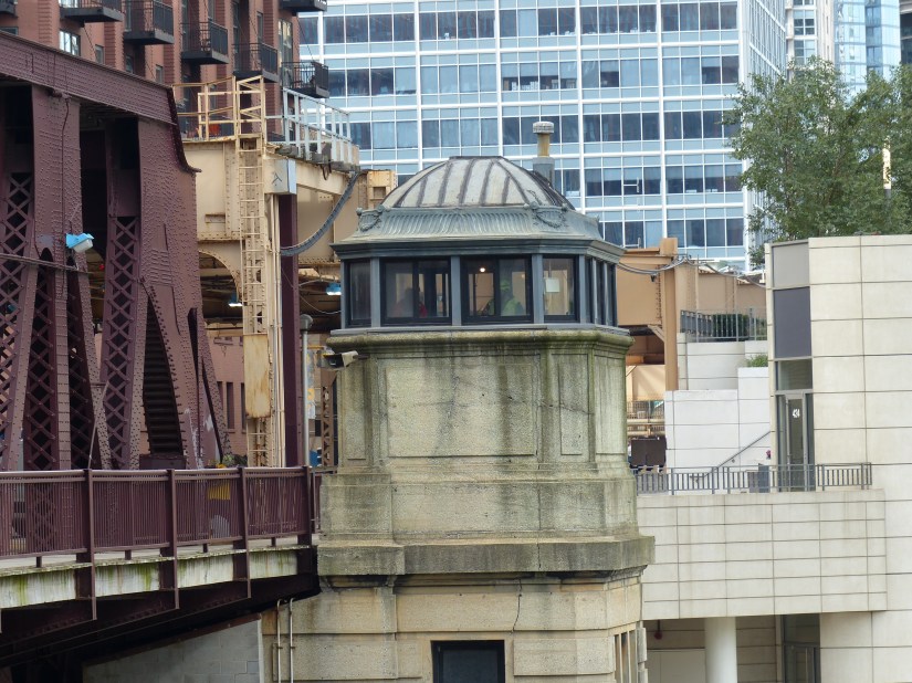
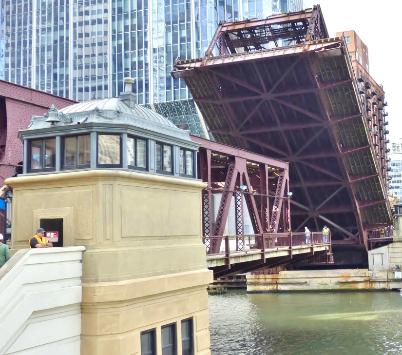
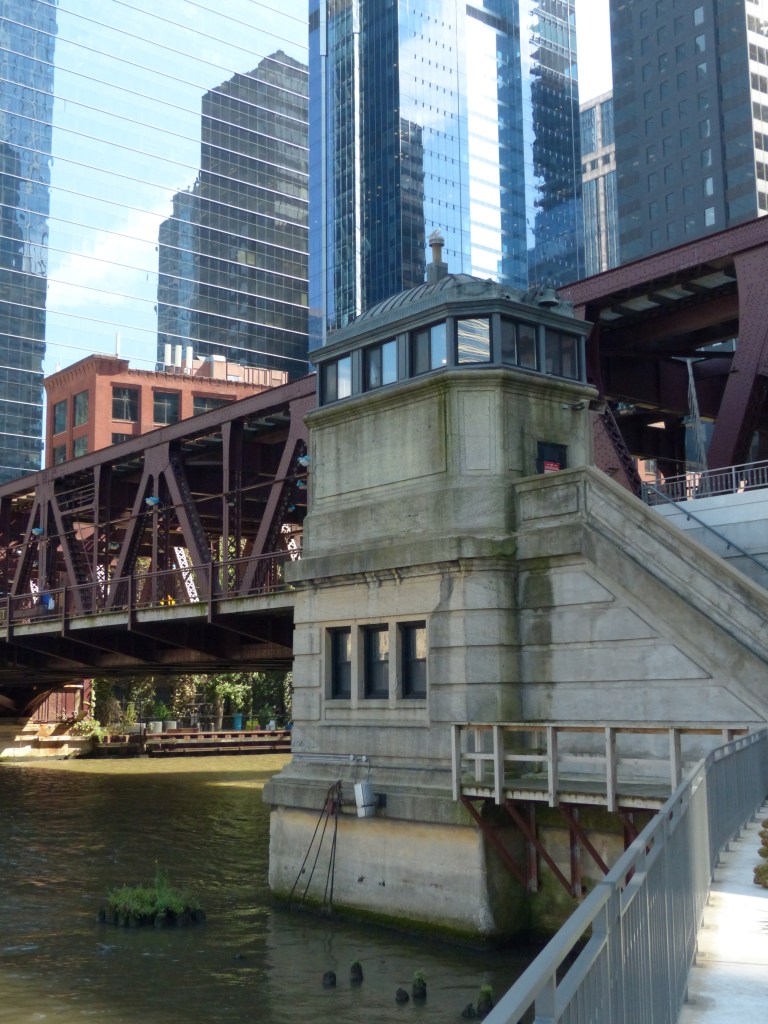
IV. The Bridge Tender’s Houses
The bridge tender’s houses are the control centers of bridge operations. Crew members enter the houses and communicate with others around the bridge area to ensure public safety during all stages of bridge lifts. The two houses are designed with Beaux-Arts and Neoclassical elements used in Chicago for bridge houses between 1900 and the 1930s.
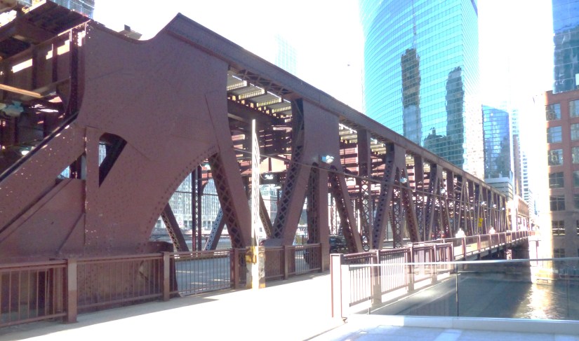
V. The Substructure. The Cast of Supporting Members
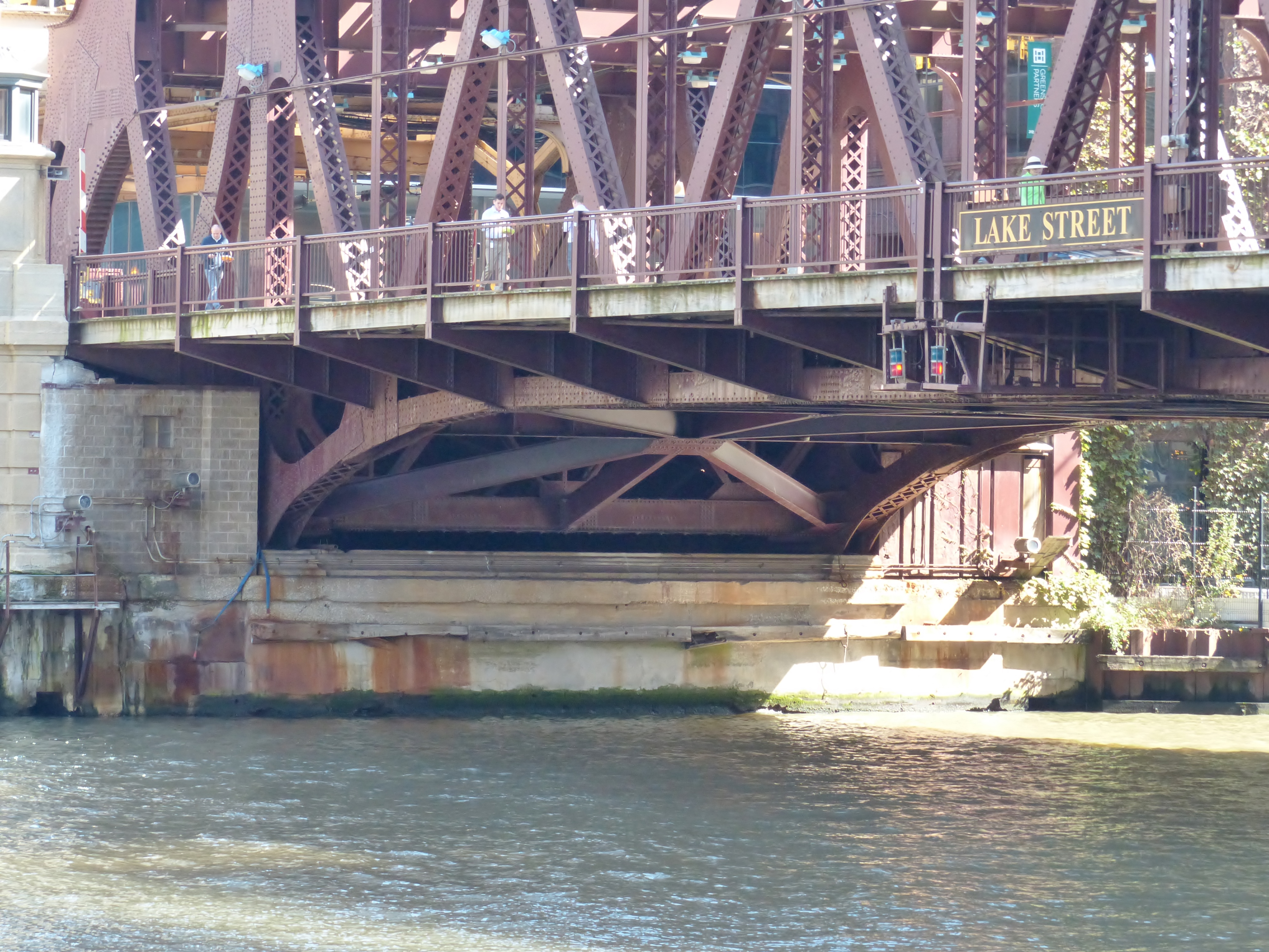
Bridge Lifts Show Substructure Elements

Sidebar: What Road‑Deck Stringers Do on a Bascule Bridge
Road‑deck stringers are the longitudinal beams that run in the direction of traffic, directly beneath the roadway. On a bascule bridge—especially a heavy Chicago trunnion bascule like Lake Street—they play a quiet but essential role in how the deck carries load and how the leaf behaves during a lift.
🚗 1. They Carry Wheel Loads to the Floor beams
Stringers are the first structural members to receive the concentrated loads from cars, trucks, buses, and maintenance vehicles.
- They spread those loads along their length.
- Then they deliver the loads into the transverse floor beams, which in turn transfer them into the truss or girder system of the leaf.
Without stringers, the deck would behave like a thin plate—far too flexible for traffic.
🧱 2. They Stiffen the Deck and Prevent Local Bending
Because they run longitudinally and are closely spaced, stringers:
- Prevent the deck from sagging between floor beams
- Reduce vibration and bounce
- Keep the riding surface smooth and predictable
On a movable leaf, this stiffness is even more important because the deck is not continuously supported like a fixed span.
⚙️ 3. They Help the Leaf Act as a Single Structural Unit During a Lift
When the bascule leaf rotates upward, the entire superstructure is in a different load regime.
Stringers help:
- Maintain torsional rigidity of the deck
- Keep the floor system acting as a unified panel
- Prevent twisting or racking as the leaf rises
🔩 4. They Tie Into the Floor System and Truss Nodes
On Lake Street Bridge’s west leaf:
- Each stringer frames into a floor beam
- Each floor beam frames into a truss panel point
- The truss carries the loads to the trunnion and heel joint
So the stringers are the first link in the load path that ultimately reaches the bascule machinery.
🛠️ 5. They Support the Wearing Surface and Utilities
Stringers also carry:
- The concrete deck or steel‑grid deck
- Utility conduits
- Drainage scuppers
- Maintenance walkways (depending on the leaf)
They’re the “backbone” that everything else attaches to.
The Load Path
Stringers → Floor beams → Truss Panel Points → Bascule Machinery → Substructure
This hierarchy is what makes a movable bridge behave like a single, predictable structural unit—even while rotating 70+ feet into the air.
Bridge house (Tender’s House)
A small operational building located at the corner of a movable bridge, housing the controls and personnel responsible for raising and lowering the bridge. Chicago’s early‑20th‑century bridge houses often combine Beaux‑Arts architectural massing with industrial fenestration.
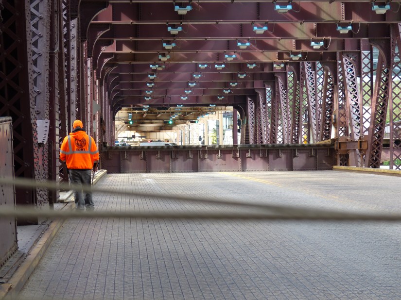
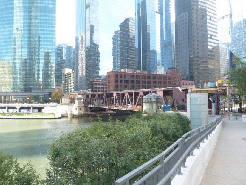
VI. Lake Street Bridge: Historic Infrastructure Set for Major Renovations
These photos were taken as crews prepared the bridge for years of significant renovations. All photos were taken from safe vantage points such as sidewalks and walkways near River Point and 150 N. Riverside.
Conclusion
Lake Street Bridge has served Chicago’s travelers since 1916. The double-deck, double-leaf fixed trunnion bascule span carries CTA trains on its upper deck and vehicles and pedestrians on the lower level.
The bridge is undergoing major maintenance until 2028. With careful monitoring and thoughtful renovations, the bridge will continue to serve Chicagoans for the next century.
Resources
- “Thompson’s Plat of 1830.” Encyclopedia of Chicago, Accessed 23 Mar. 2026.
- Wikipedia contributors. “Muntin.” Wikipedia, The Free Encyclopedia. Wikipedia, The Free Encyclopedia, 11 Dec. 2025. Web. 23 Mar. 2026.
- Copilot. “Schematic Diagram of Load Paths on Lake Street Bridge.” Microsoft Copilot, 24 Mar. 2026.
- Copilot. “Kid‑Friendly Glossary: X‑Brace, Portal Frame, and Lateral Bracing.
- Wikipedia contributors. “Terne.” Wikipedia, The Free Encyclopedia. Wikipedia, The Free Encyclopedia, 7 Dec. 2025. Web. 25 Mar. 2026.
- Copilot. “Explanation of the Lateral Braces Under the Train Deck Approach Span of the Lake Street Bridge.” Microsoft Copilot, 25 Mar. 2026.
- Microsoft Copilot. “What Road‑Deck Stringers Do on a Bascule Bridge.” Lake Street Bridge Structural Documentation, 26 Mar. 2026. AI‑generated explanatory text.
- Microsoft Copilot. “Floor System Hierarchy: How Loads Move Through a Bascule Leaf.” Lake Street Bridge Structural Documentation, 26 Mar. 2026. AI‑generated explanatory text.
- Wikipedia contributors. “191 North Wacker.” Wikipedia, The Free Encyclopedia. Wikipedia, The Free Encyclopedia, 28 Feb. 2026. Web. 31 Mar. 2026.
Discover more from Frame the Works
Subscribe to get the latest posts sent to your email.
