Article and photographs by Divi Logan
About the Wells Street Bridge
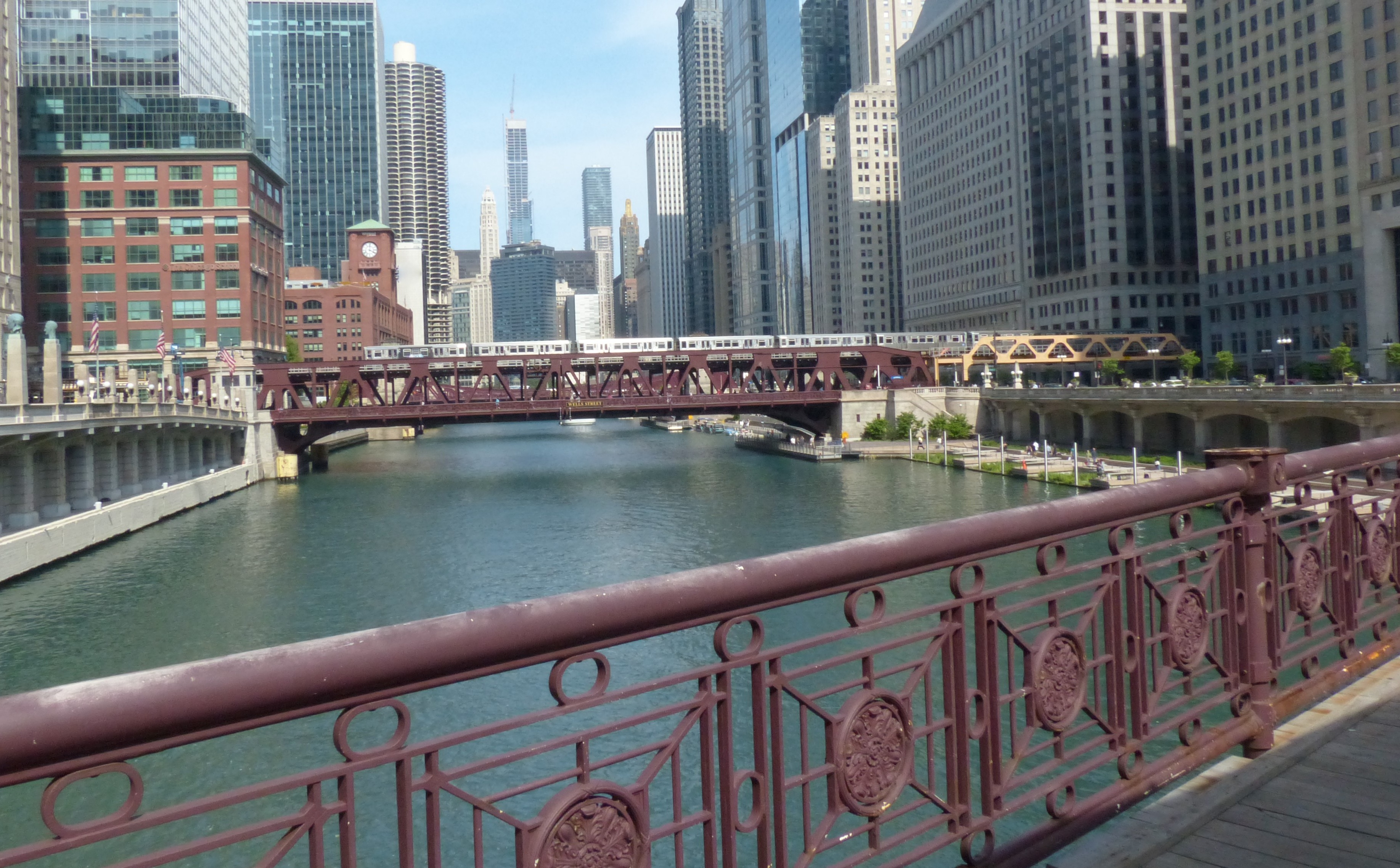
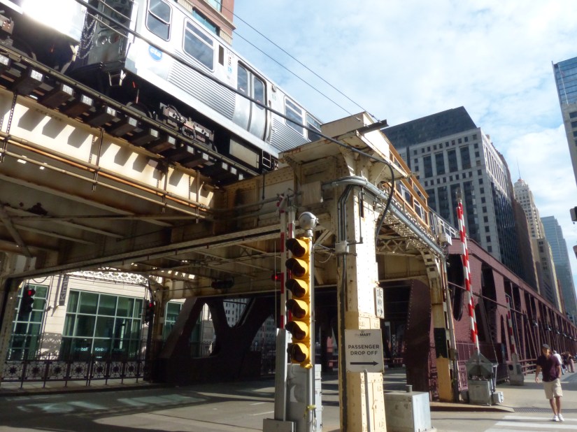
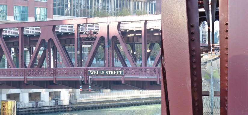
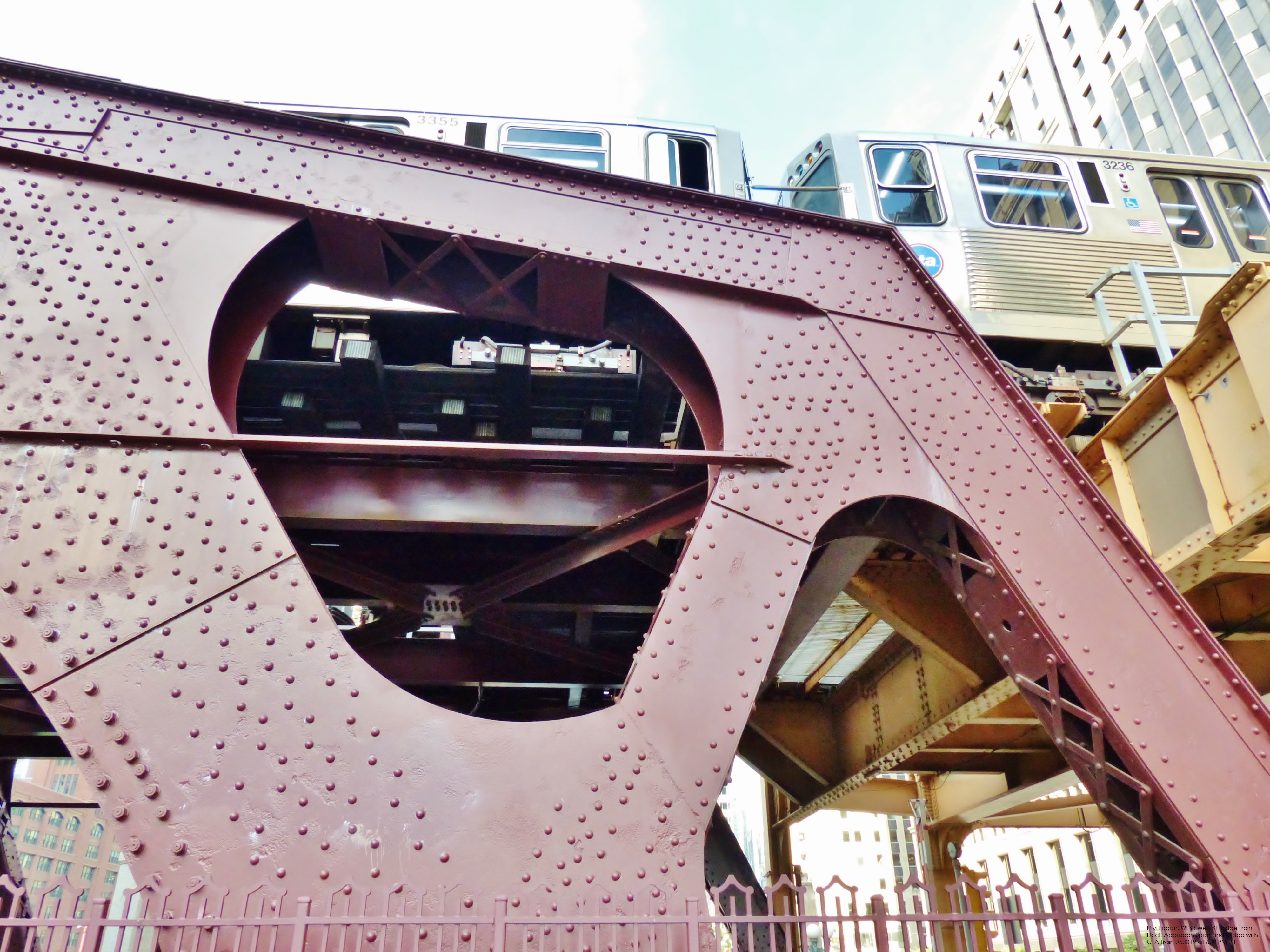
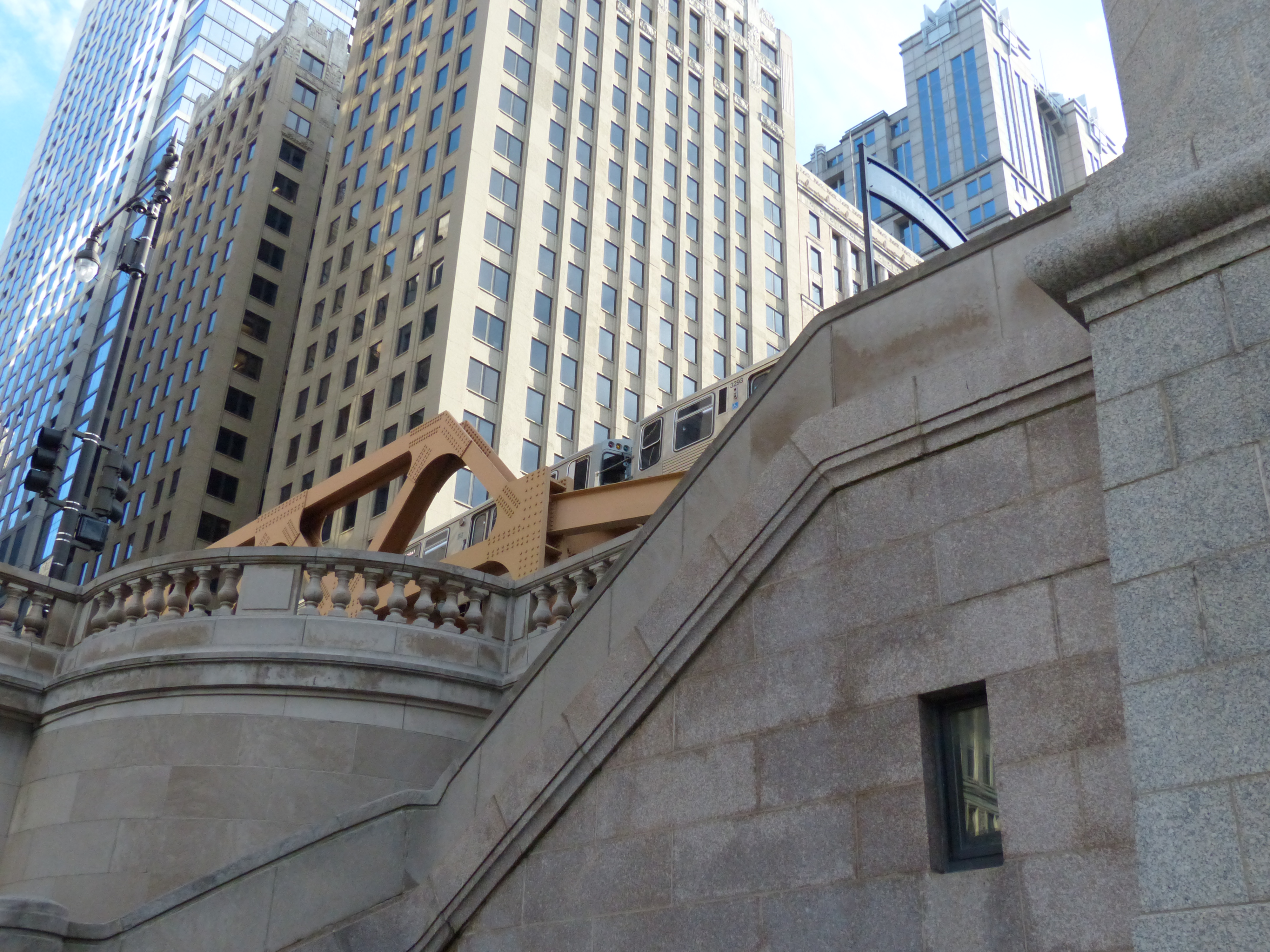
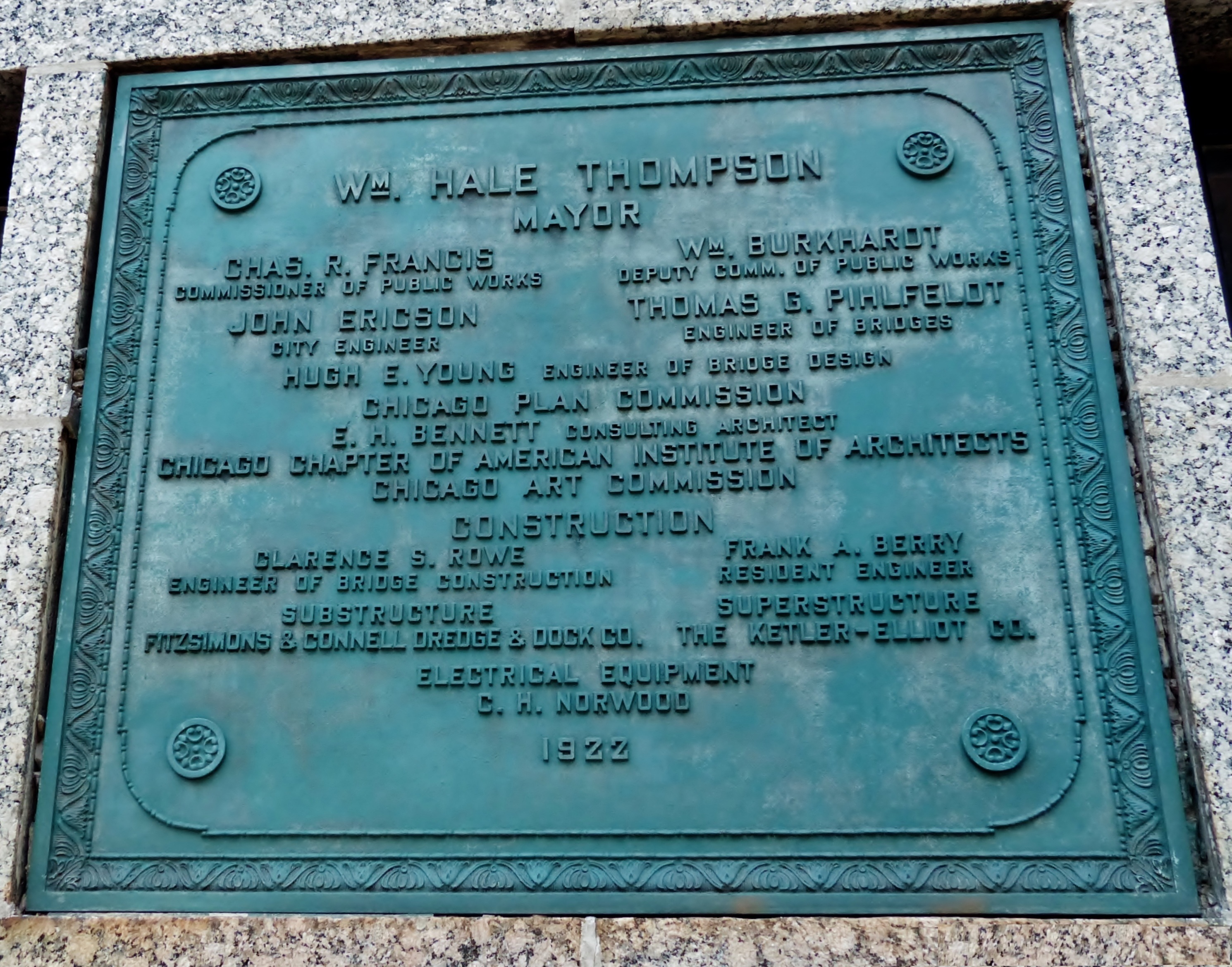
The original Wells Street Bridge opened in 1922. In 2012 – 2013 the bridge was rebuilt. It is one of two bridges in downtown Chicago that carries Chicago Transit Authority trains on its upper deck, the other being Lake Street Bridge across the river’s south branch.
Bridge specifications and details:
Fixed trunnion
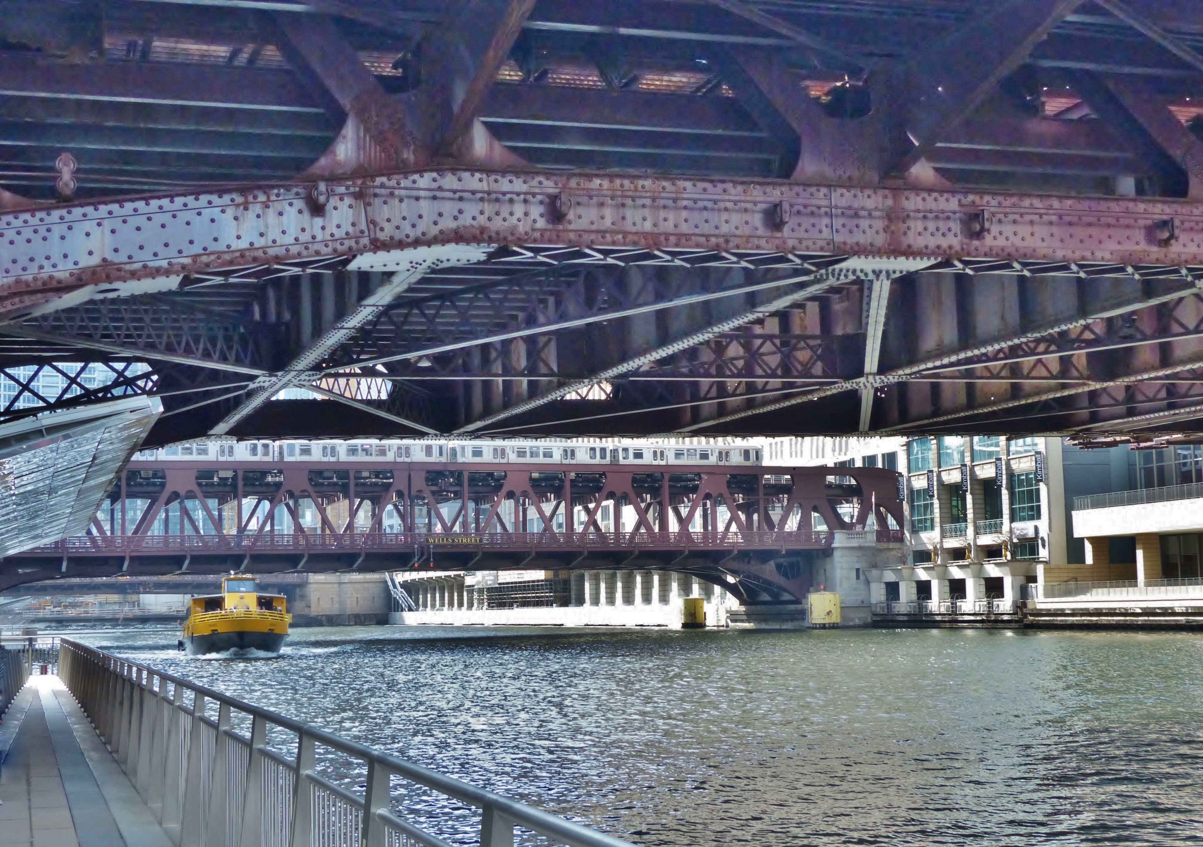
Truss Type: Warren through truss bascule
Decks and leaves: Two decks, two leaves
Carries: trains on the upper deck, vehicles and pedestrians on the lower deck
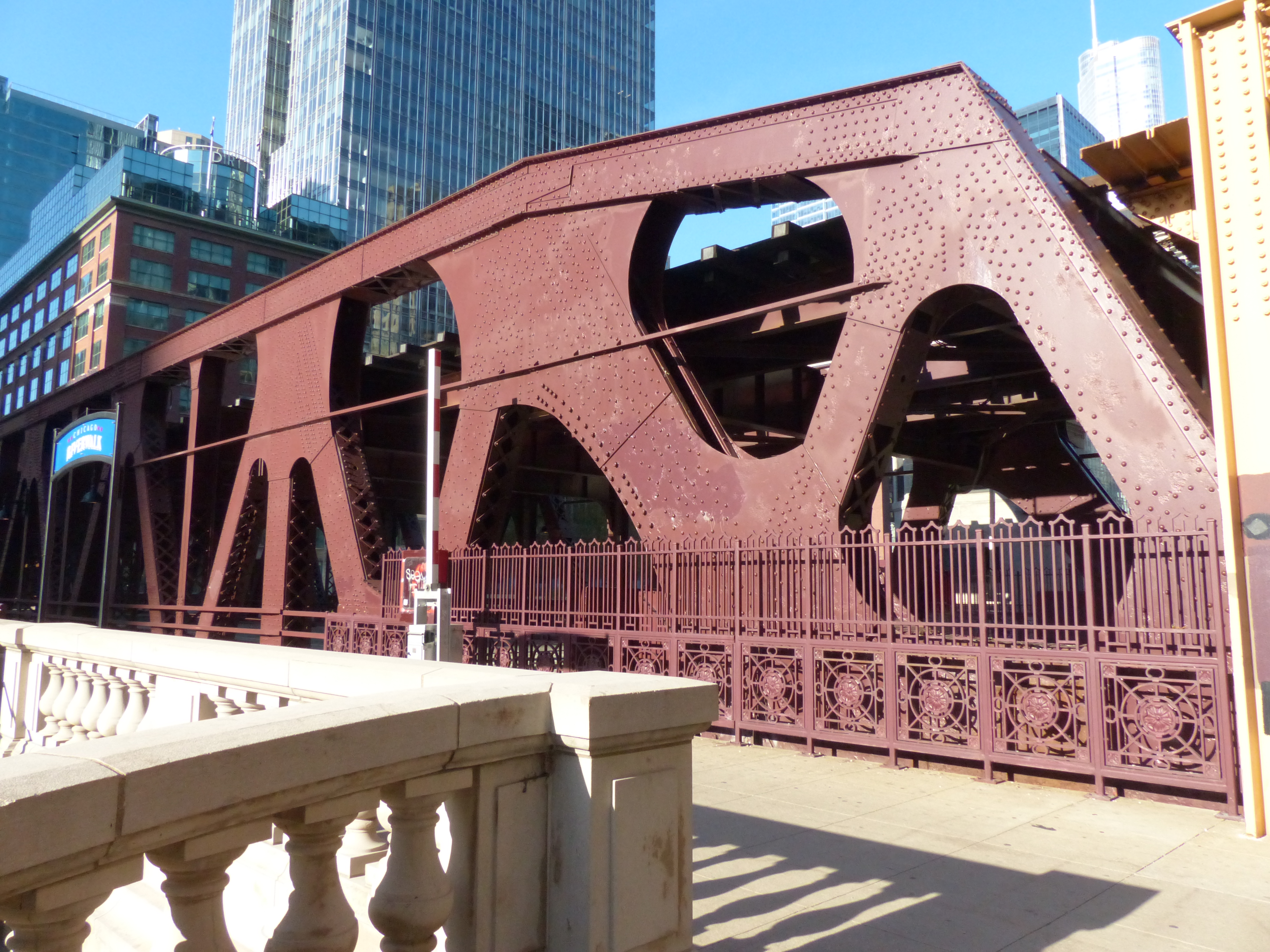
The bridge’s double-deck, double-leaf bascule design includes complex truss work with built-up members fabricated by the Fort Pitt Bridge Company.
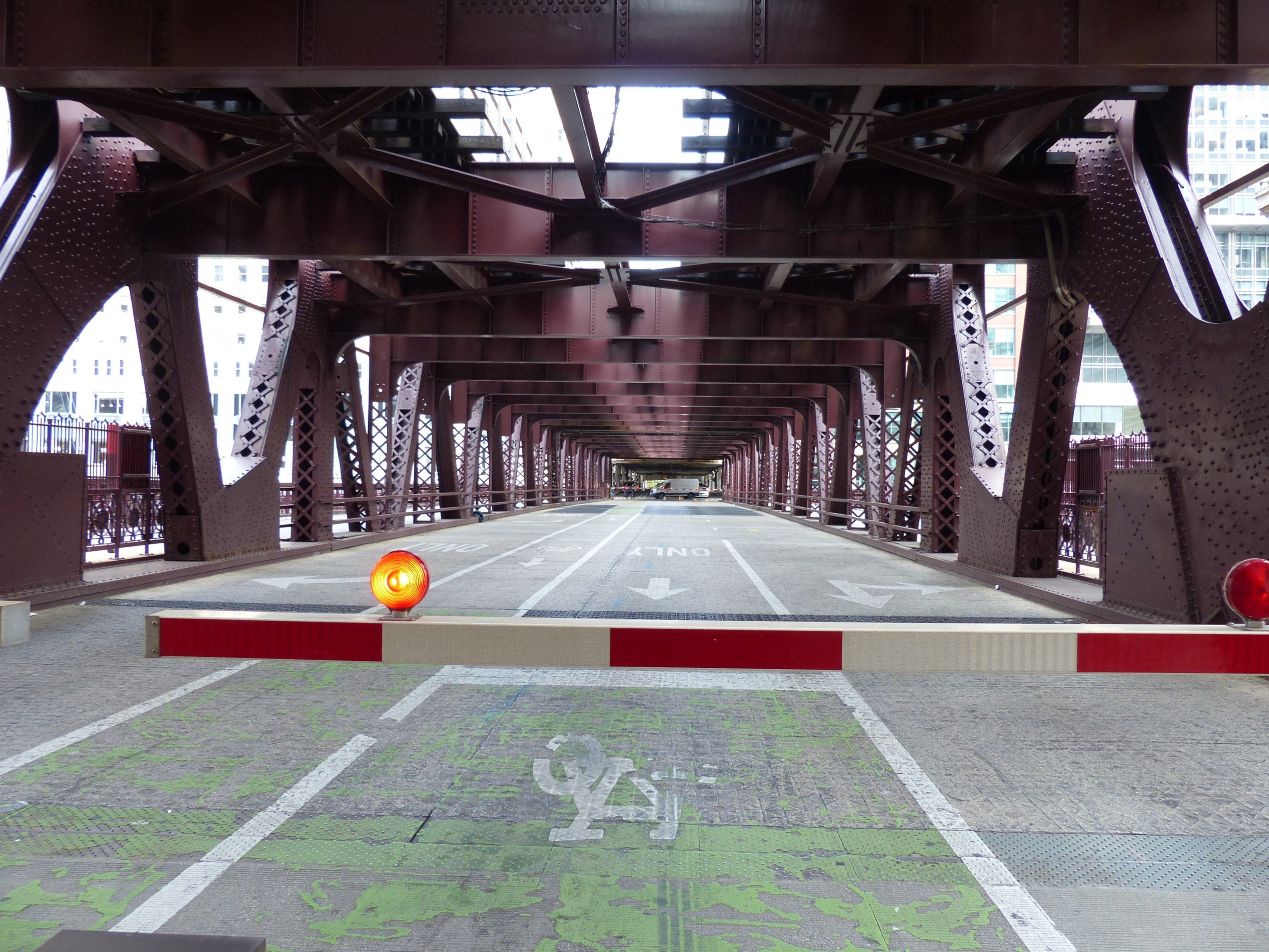
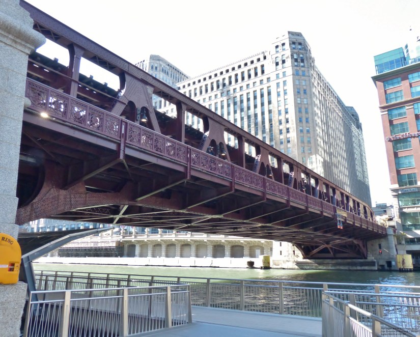
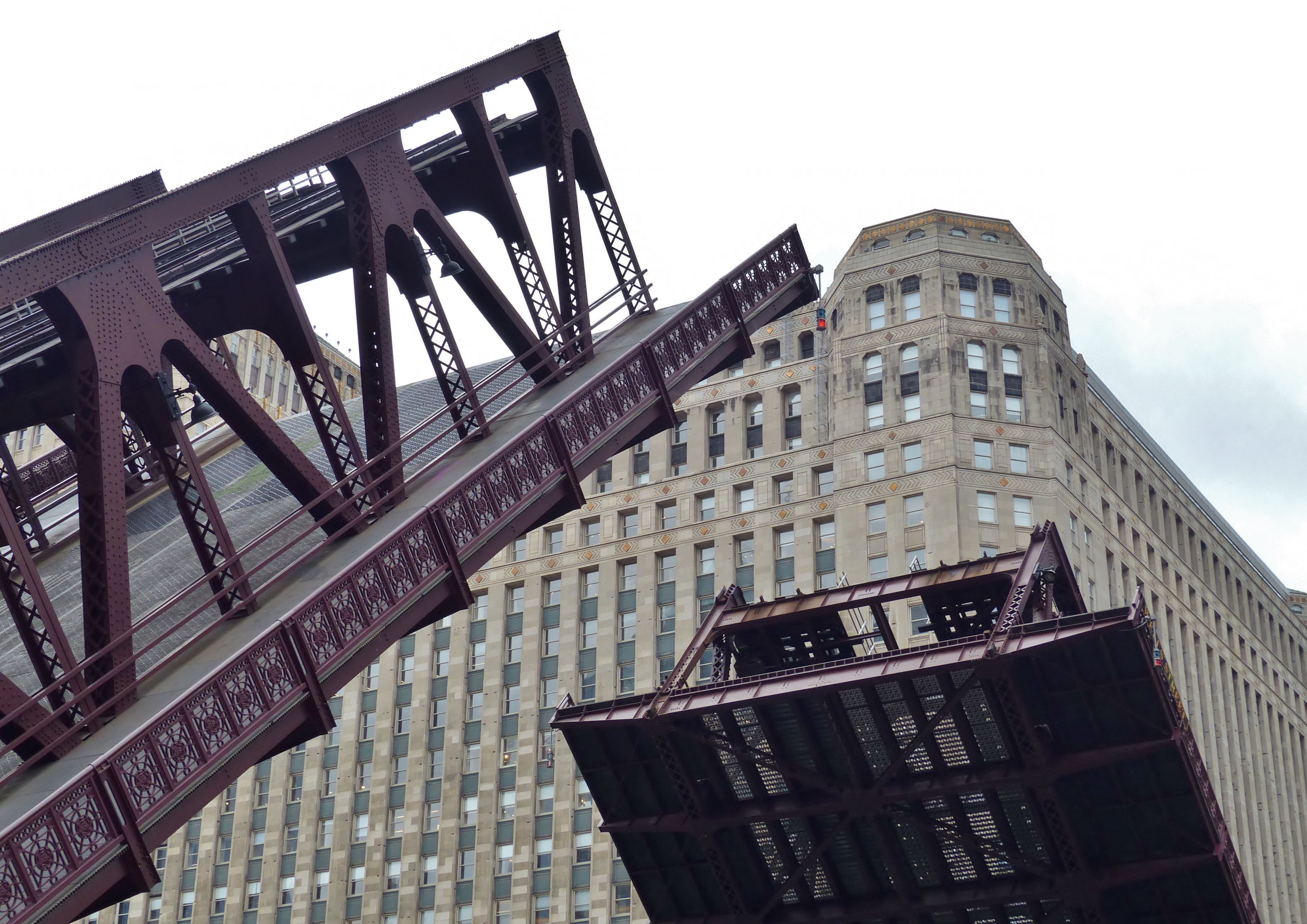
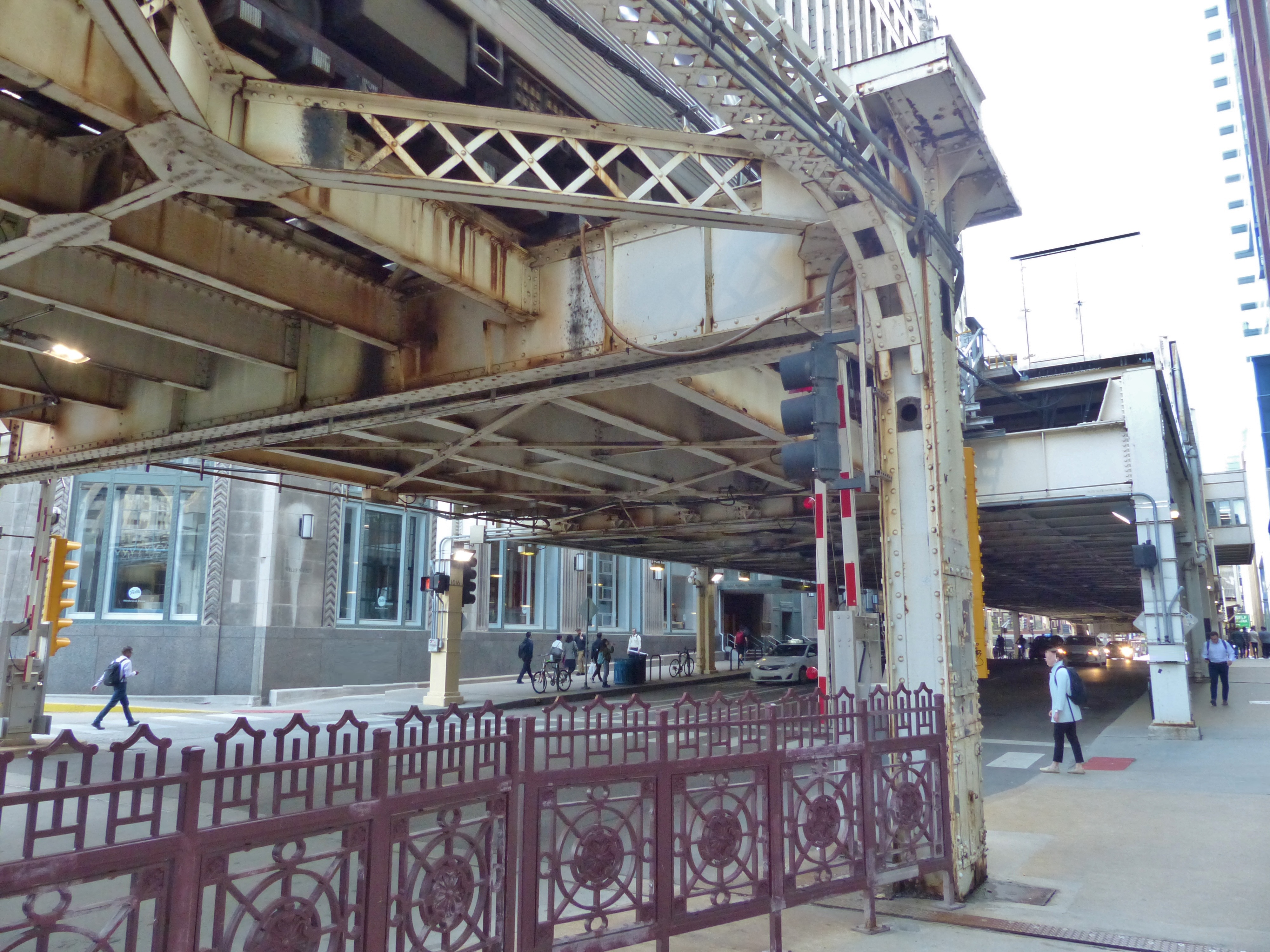
I. Approaching the Bridge: Superstructure, Train Decks, and Clear Span
The civil engineering challenges of the Chicago River’s winding courses and shallow depths required the use of movable bridges to accommodate the city’s growing population, commercial shipping industry, and social connections. Many styles of bridge were tried, such as the swing and rolling lift. Center-pier spans interfered with navigation.
The challenge was answered starting around 1900 with the building of trunnion bascule bridges, defined as bascule (French for “seesaw” or balance scale), and the trunnion, which is the large axle that raises the span. The Chicago-style bascule bridge is a refinement by Joseph Strauss of the fixed-trunnion. Design variations noted in the city include the single-deck pony truss and the style discussed in this article, the double-deck, double-leaf, Warren through truss.
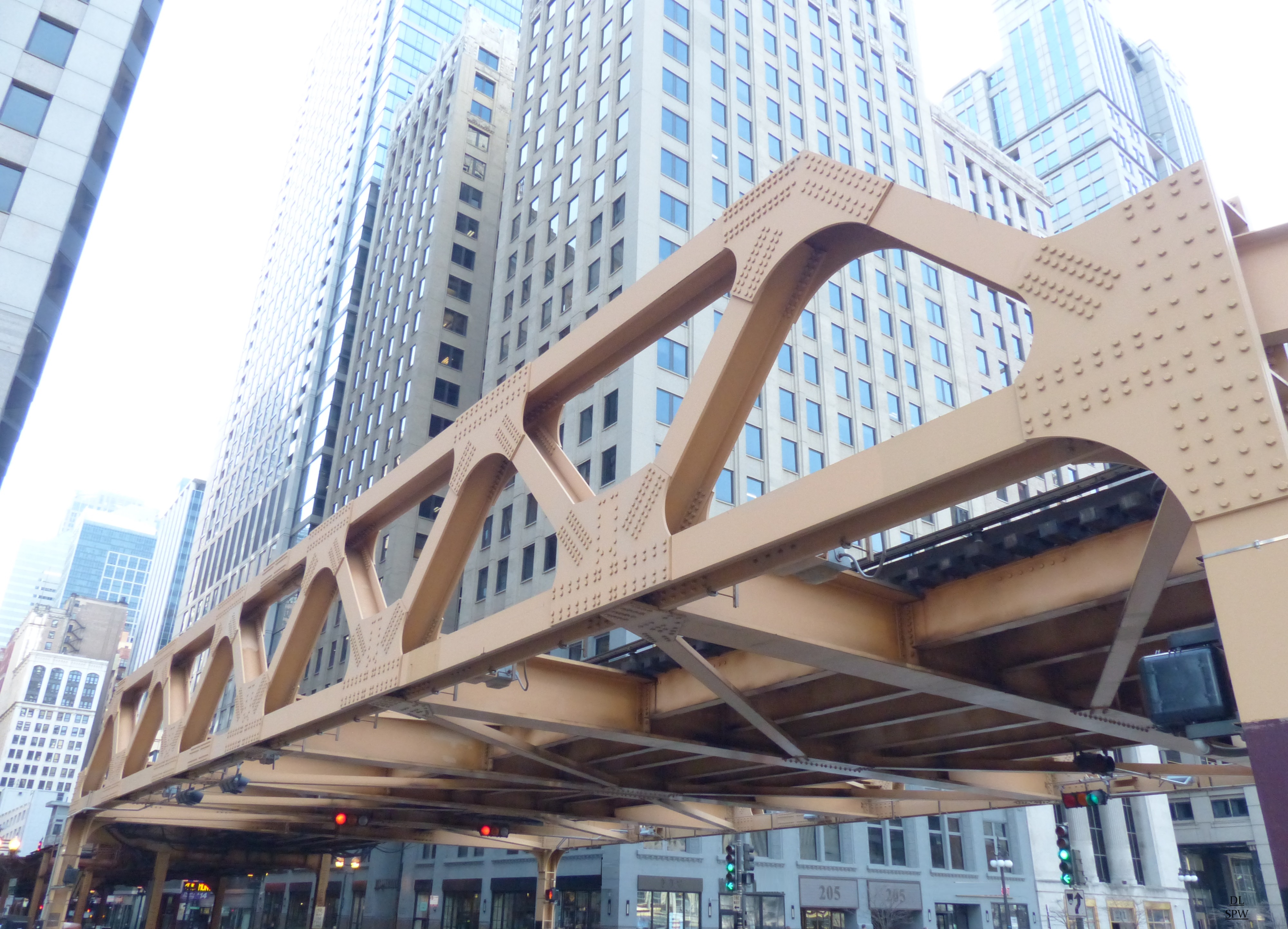
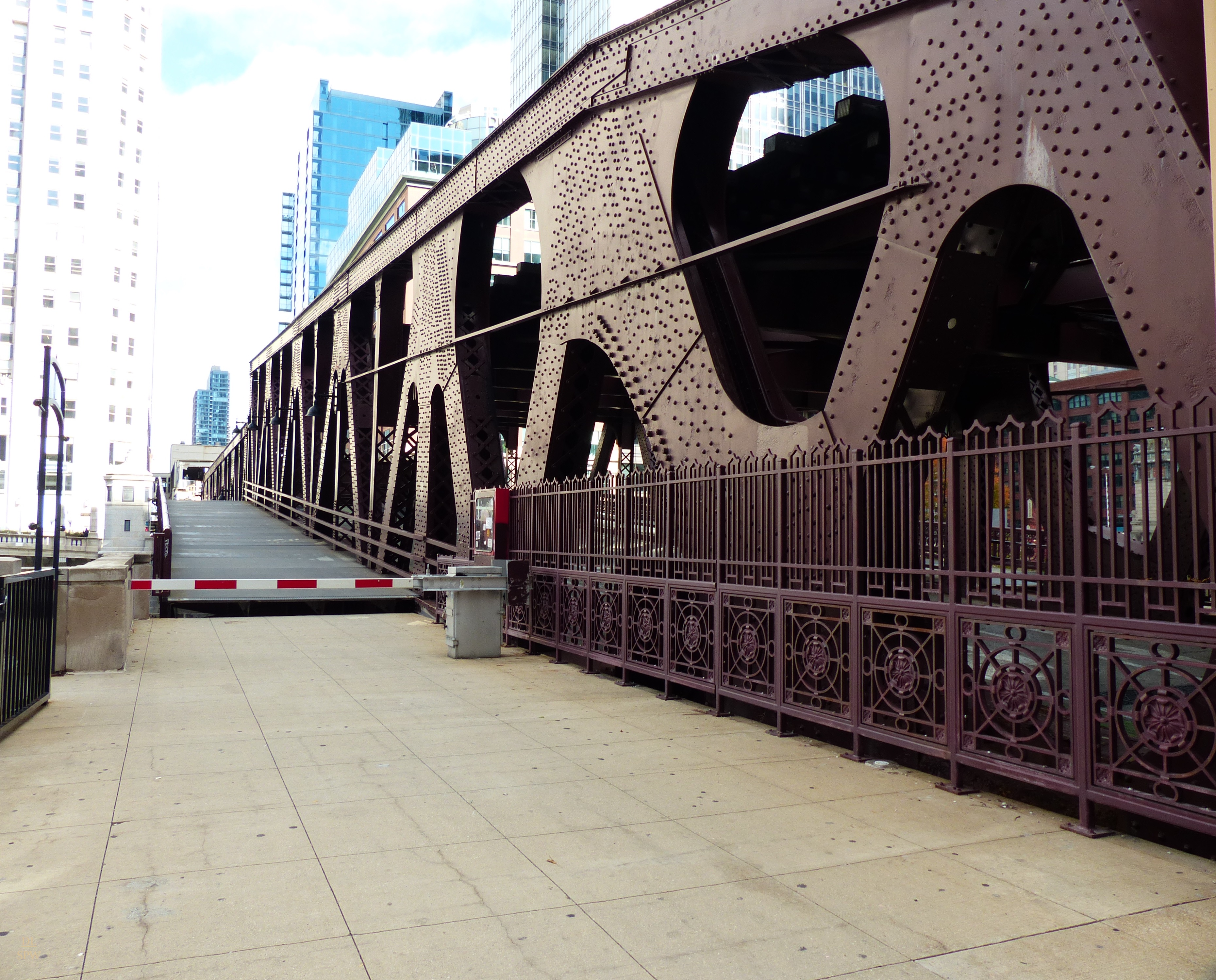
The Through Truss Bridge: Heavy Metal Connects Chicago Infrastructure
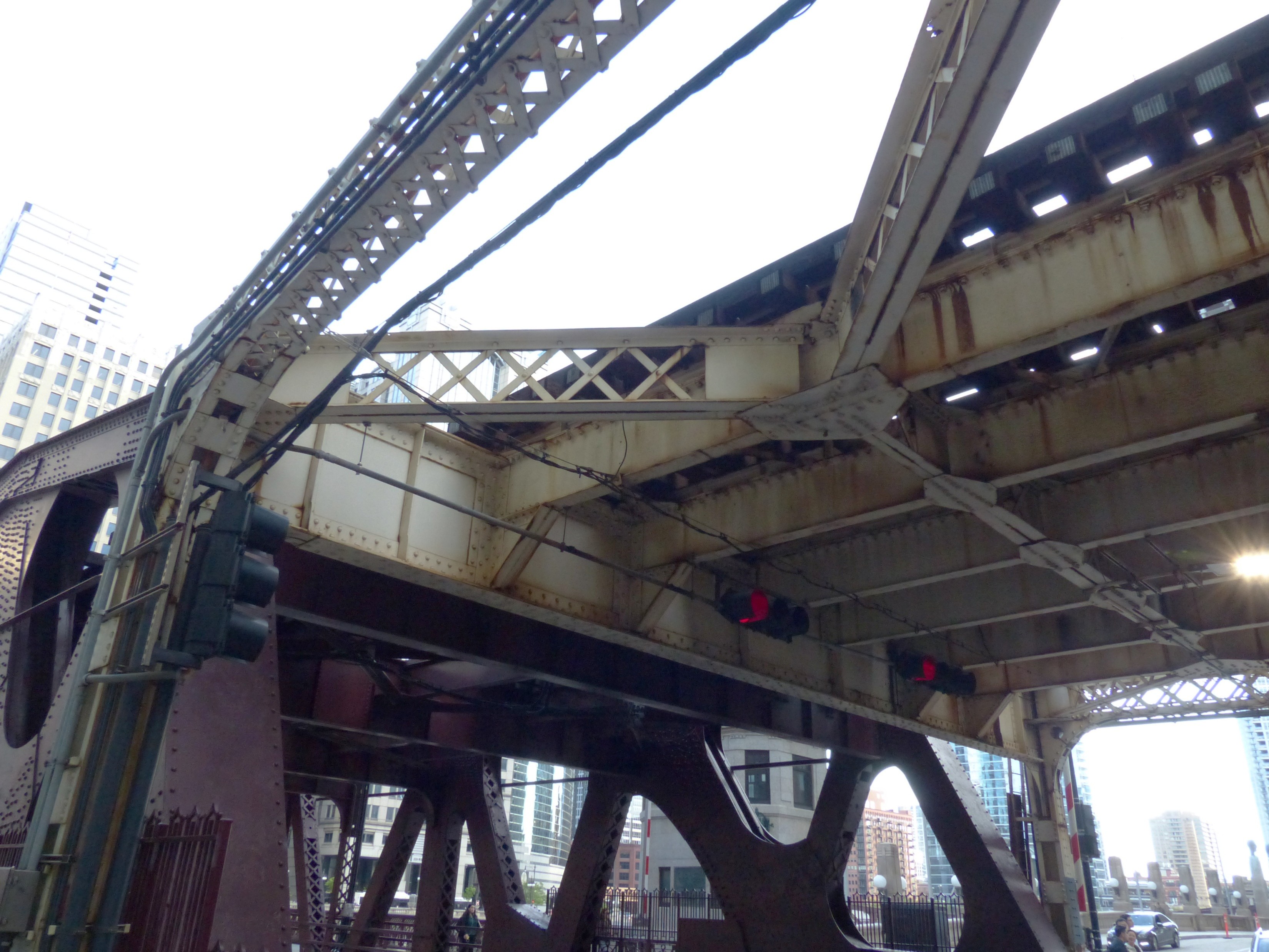
Through truss bascule bridges are connected by top and bottom chords, the longitudinal members that define the top and bottom edges of the truss. Top chords are in compression on the upper boundary, and bottom chords are usually in tension, forming the lower boundary. These are subject to significant stress during bridge operation.
- In double-deck configurations, bracing helps transfer loads between the upper and lower decks.
- It ensures that live loads (vehicles, pedestrians) are not concentrated on isolated members, reducing fatigue and stress concentrations.
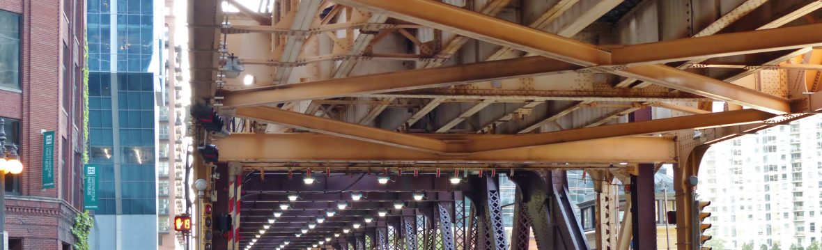
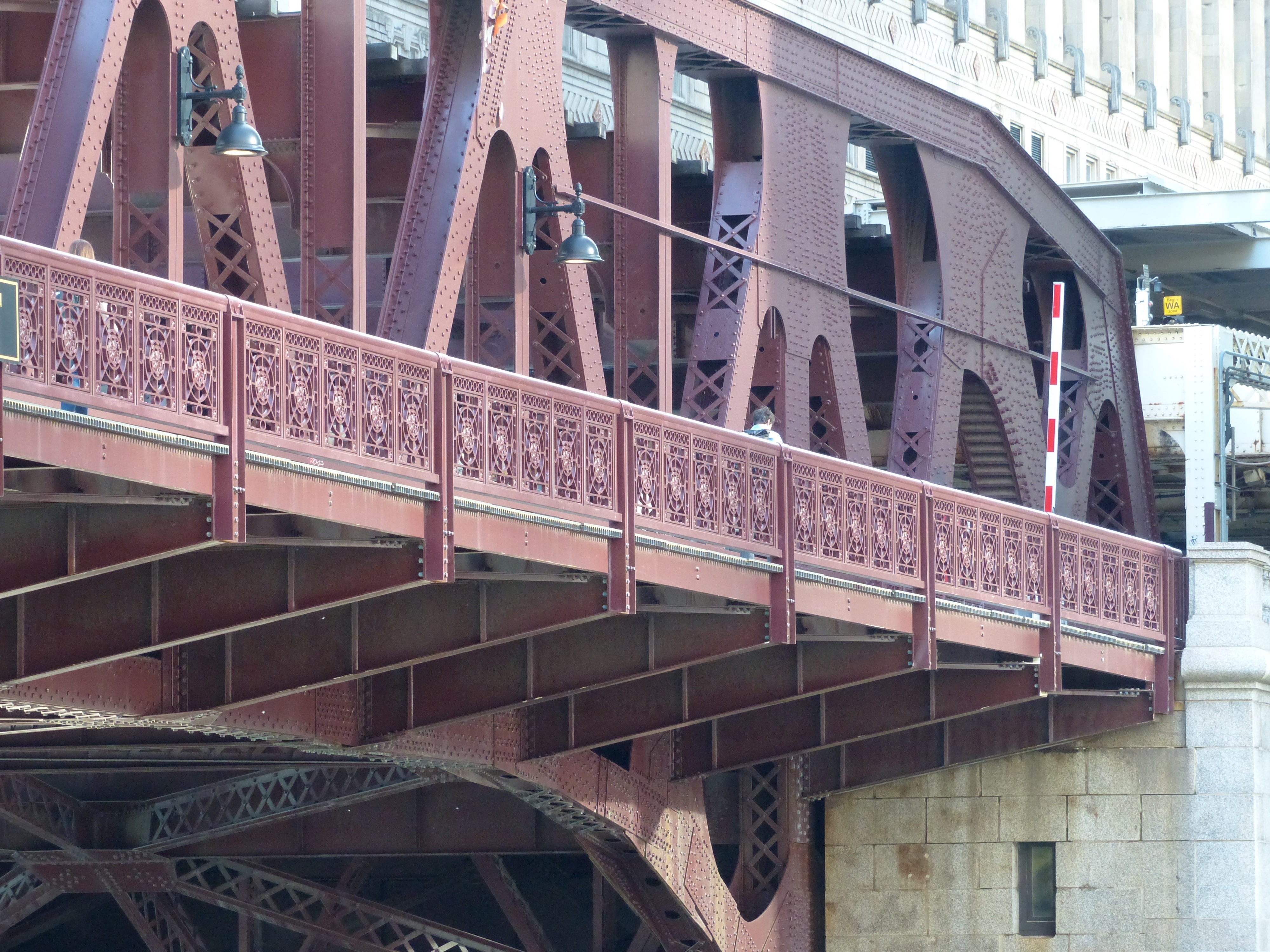
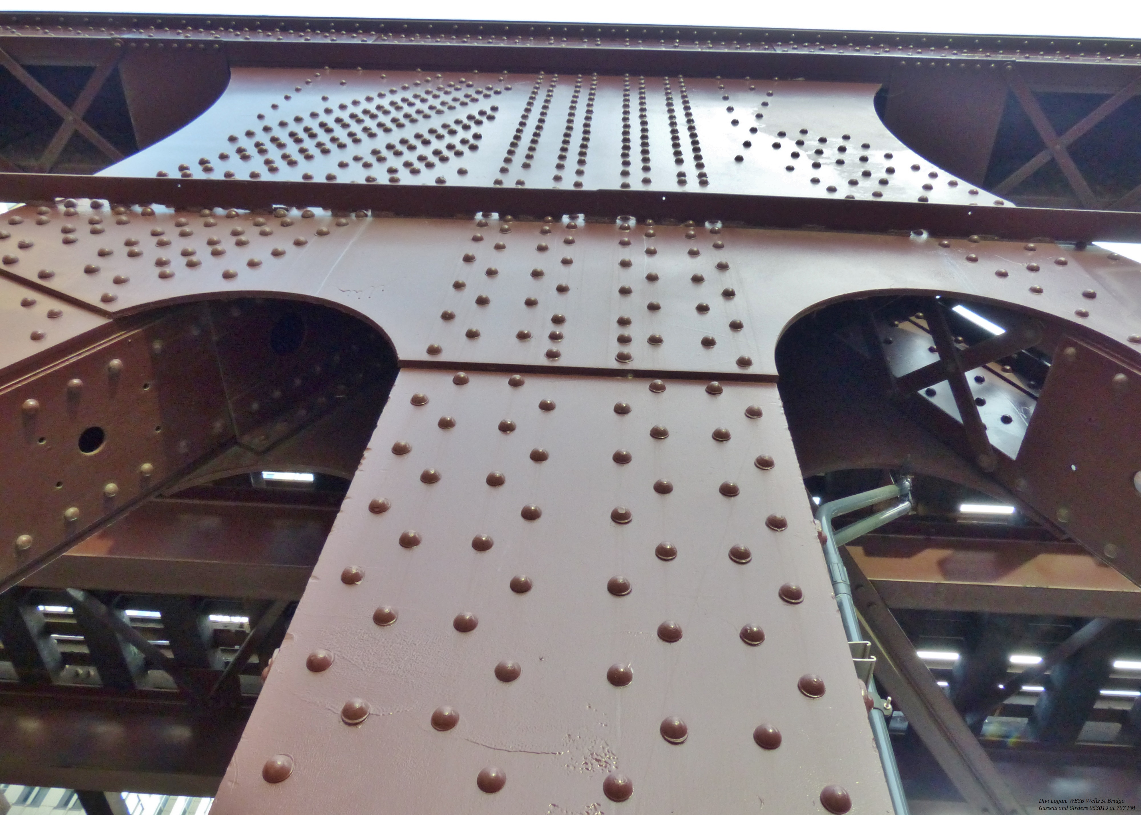
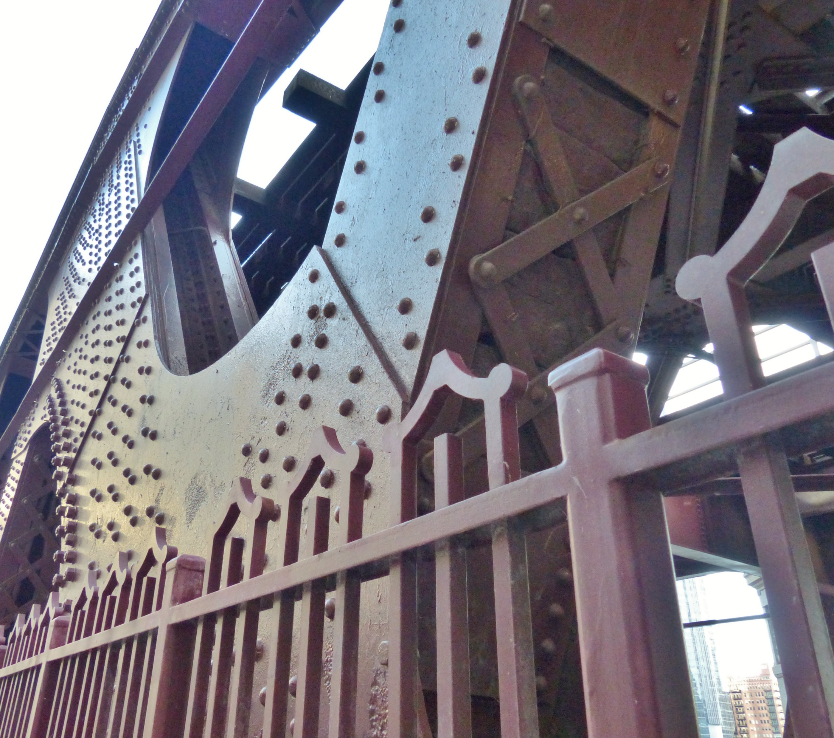
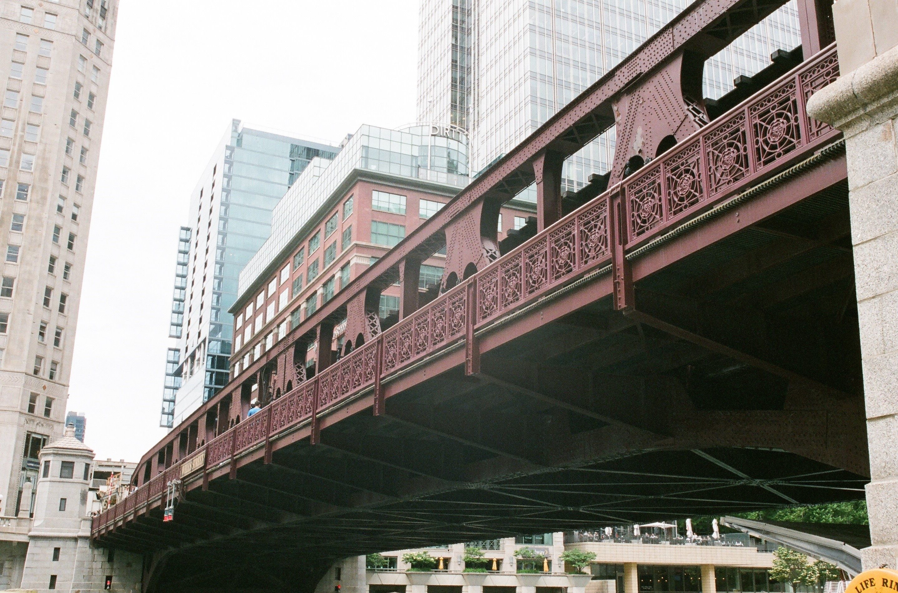
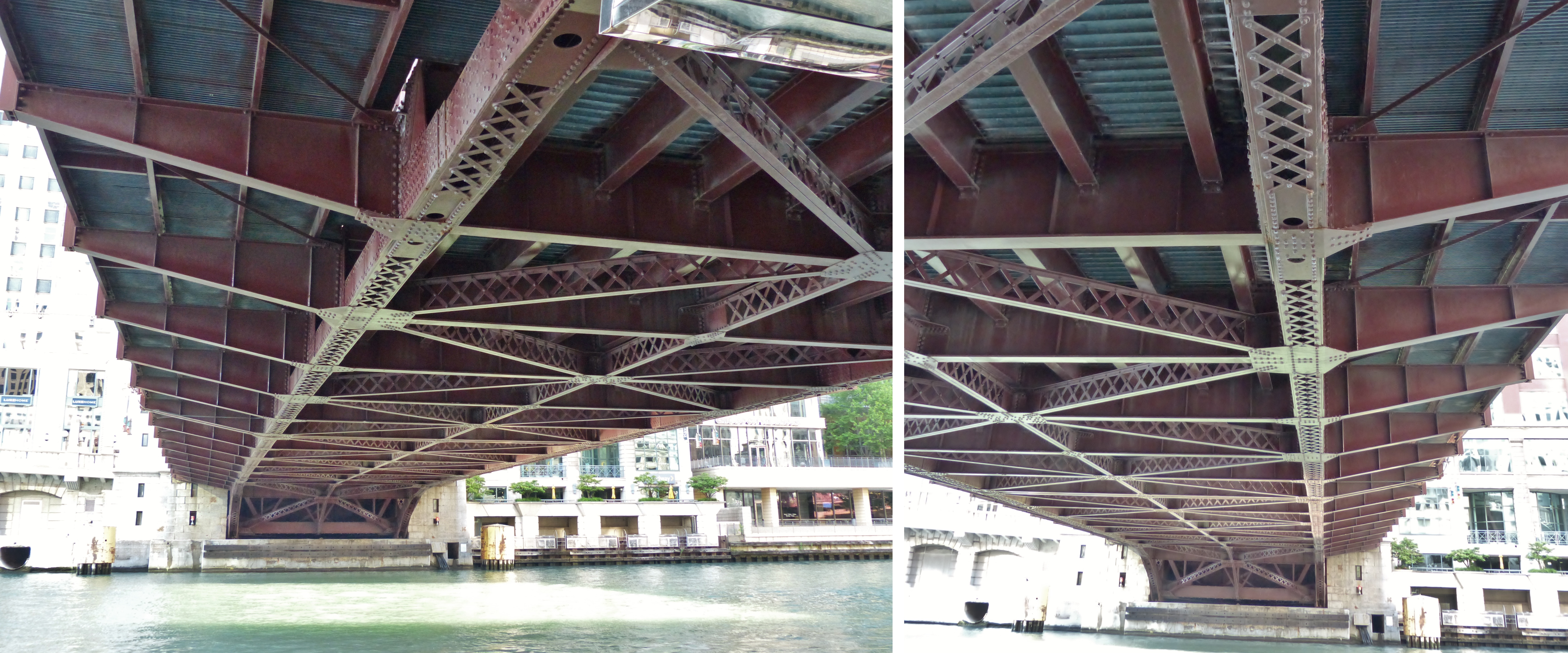
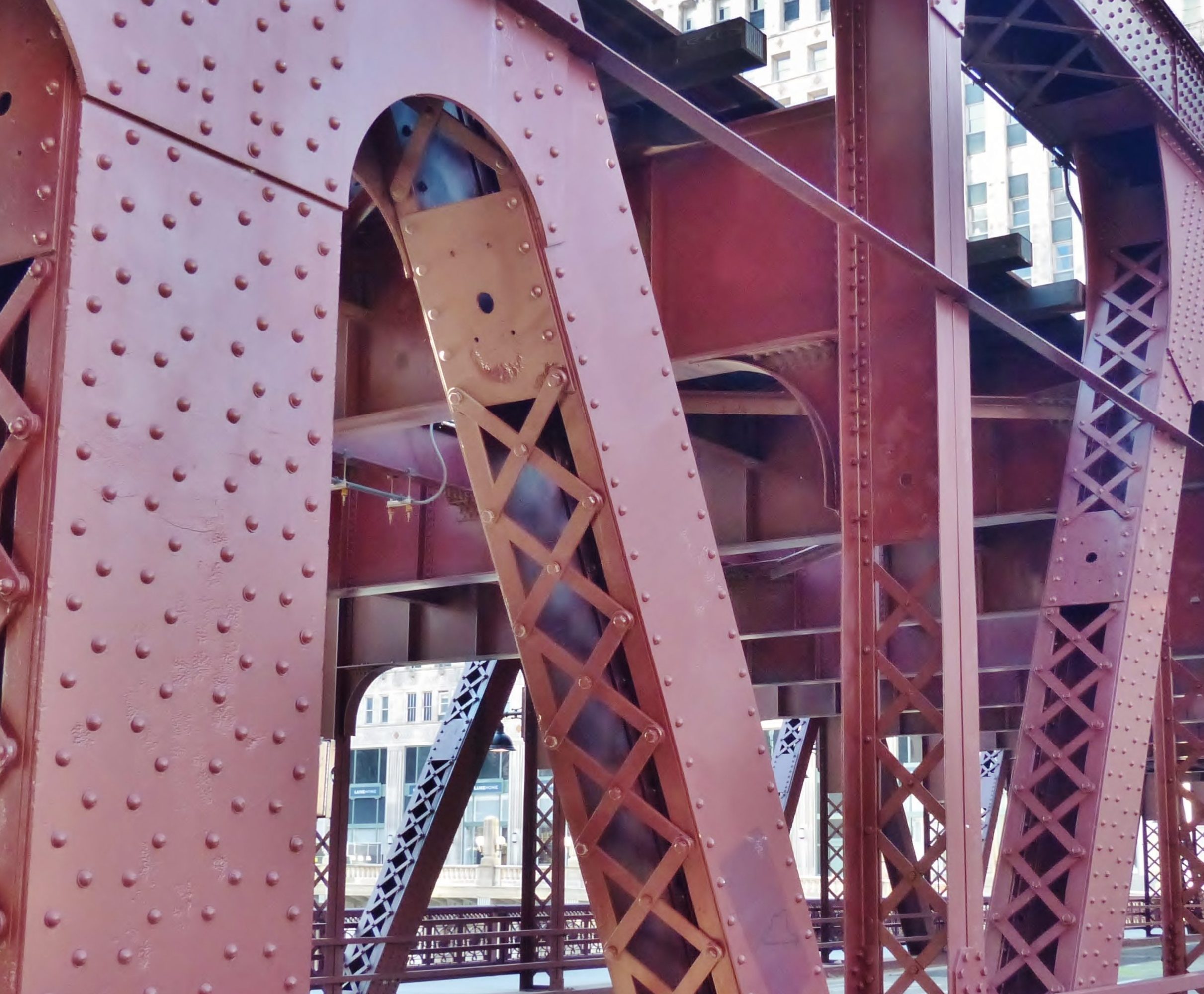
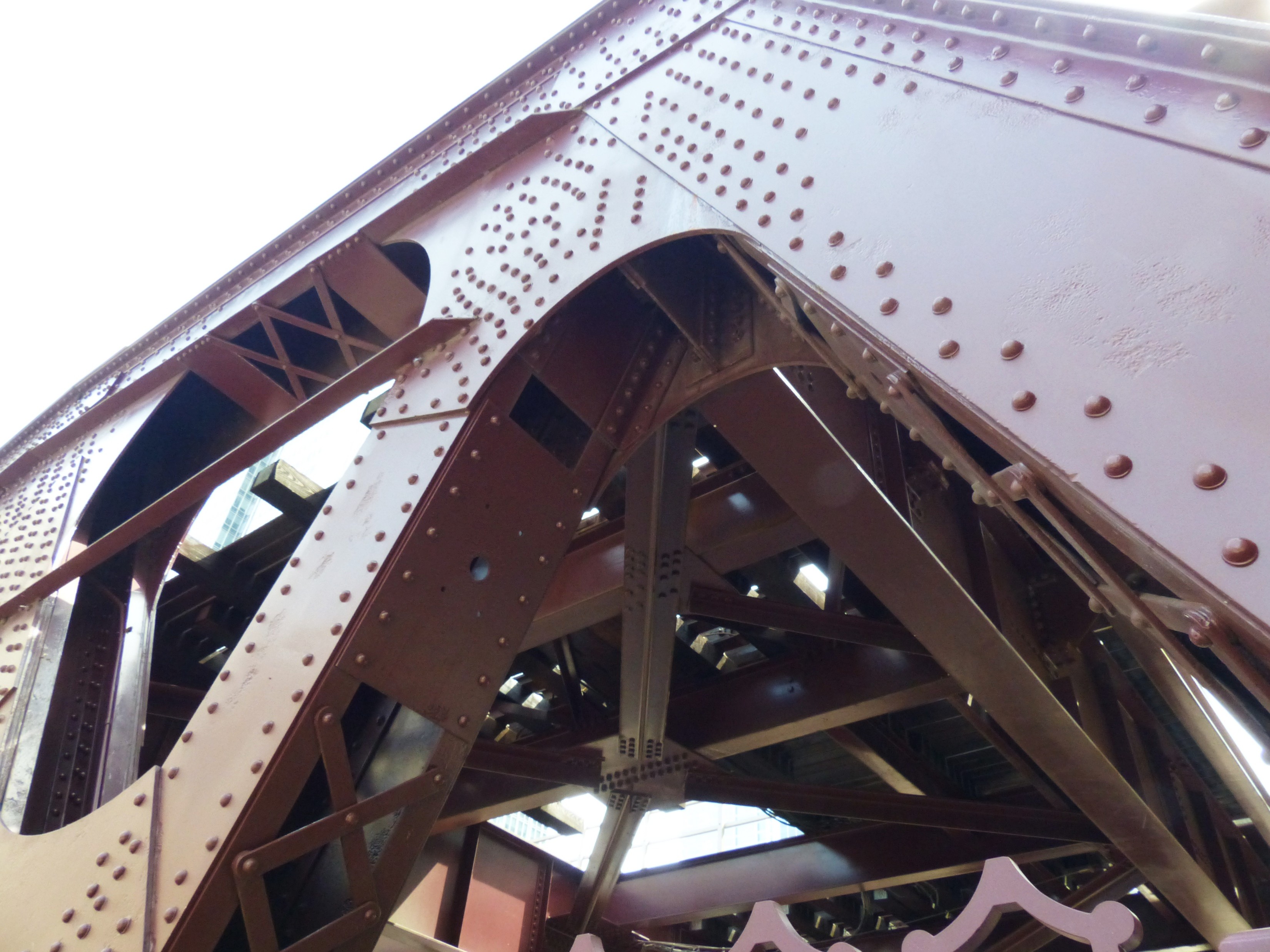
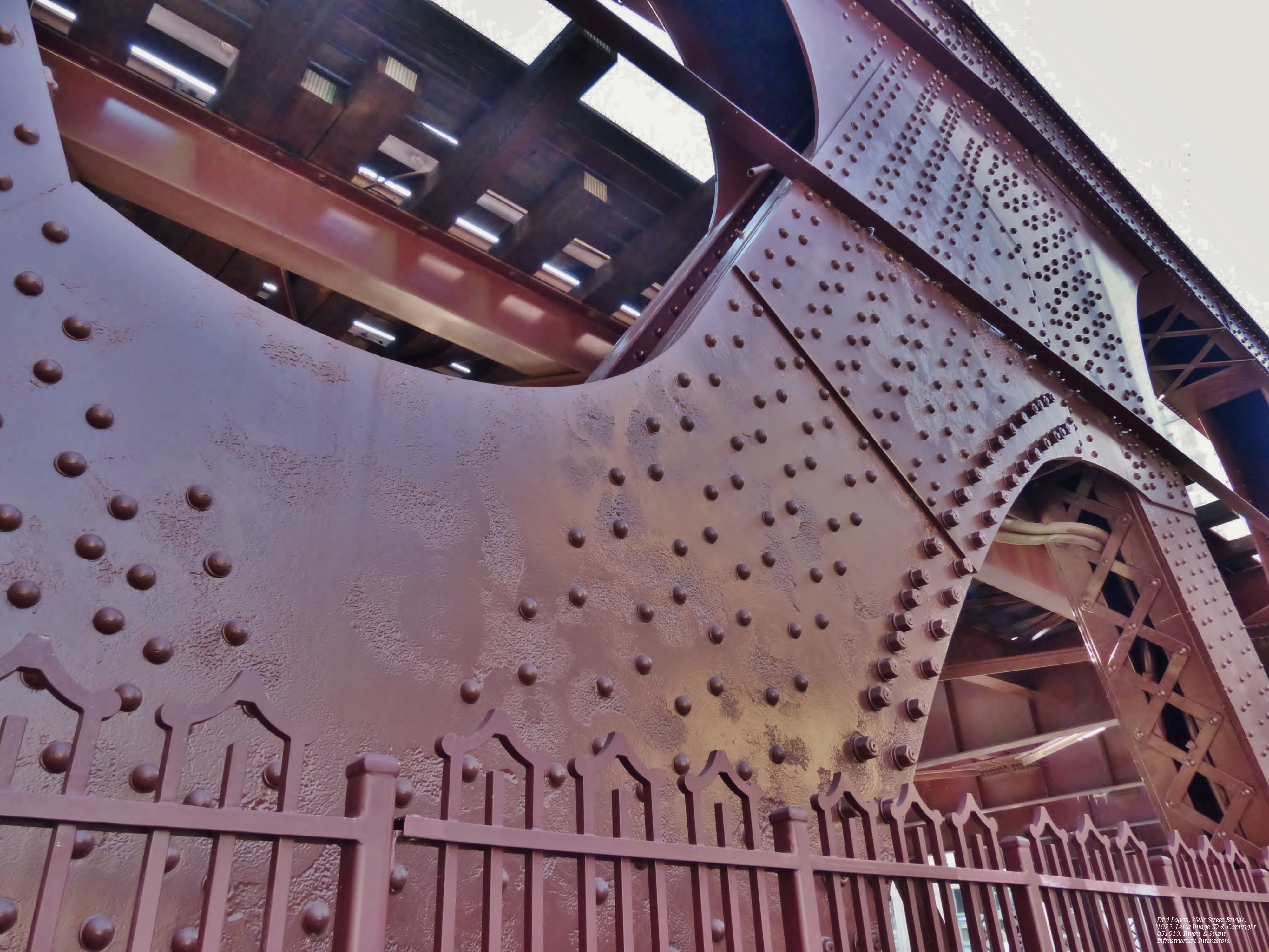
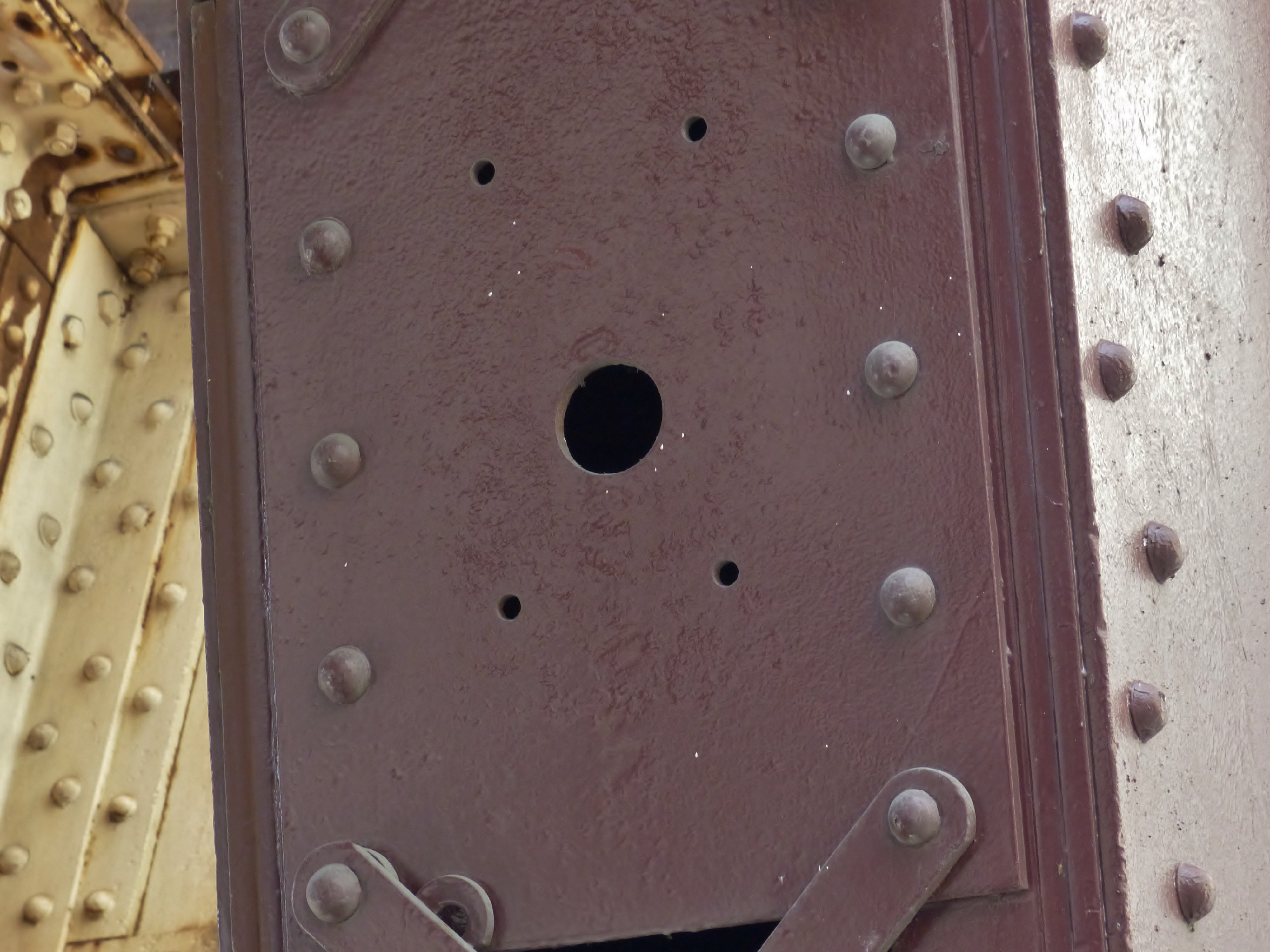
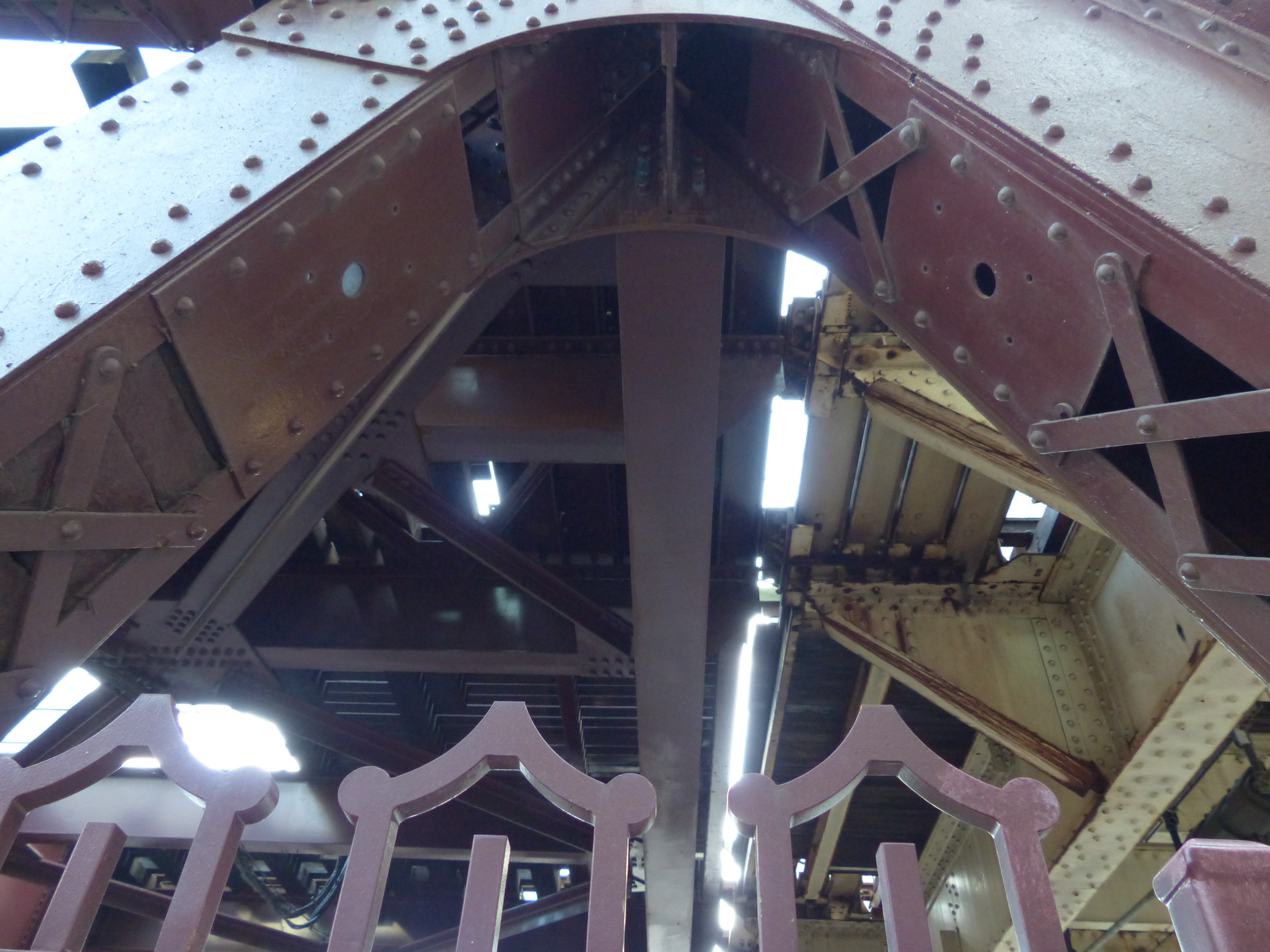
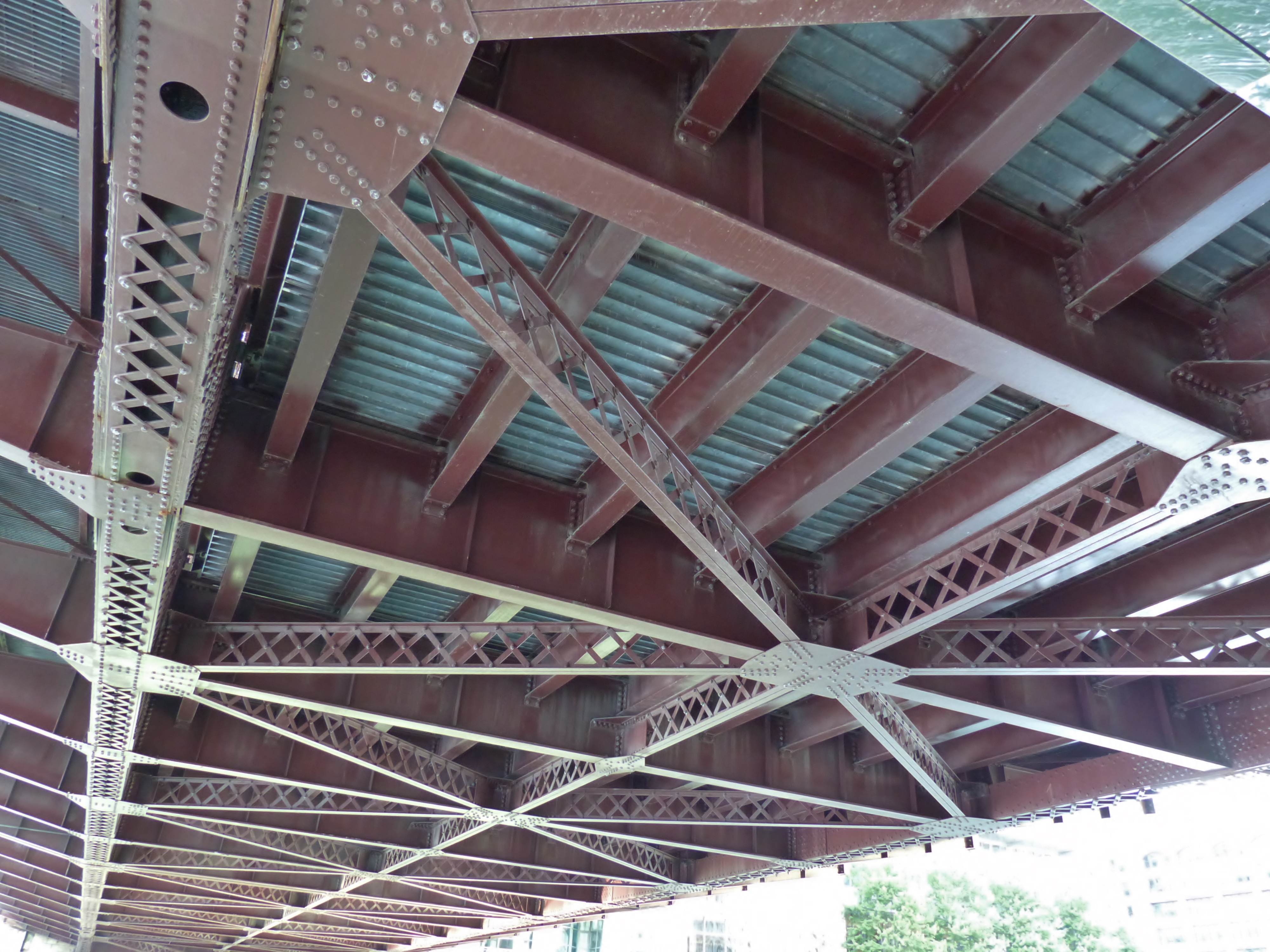
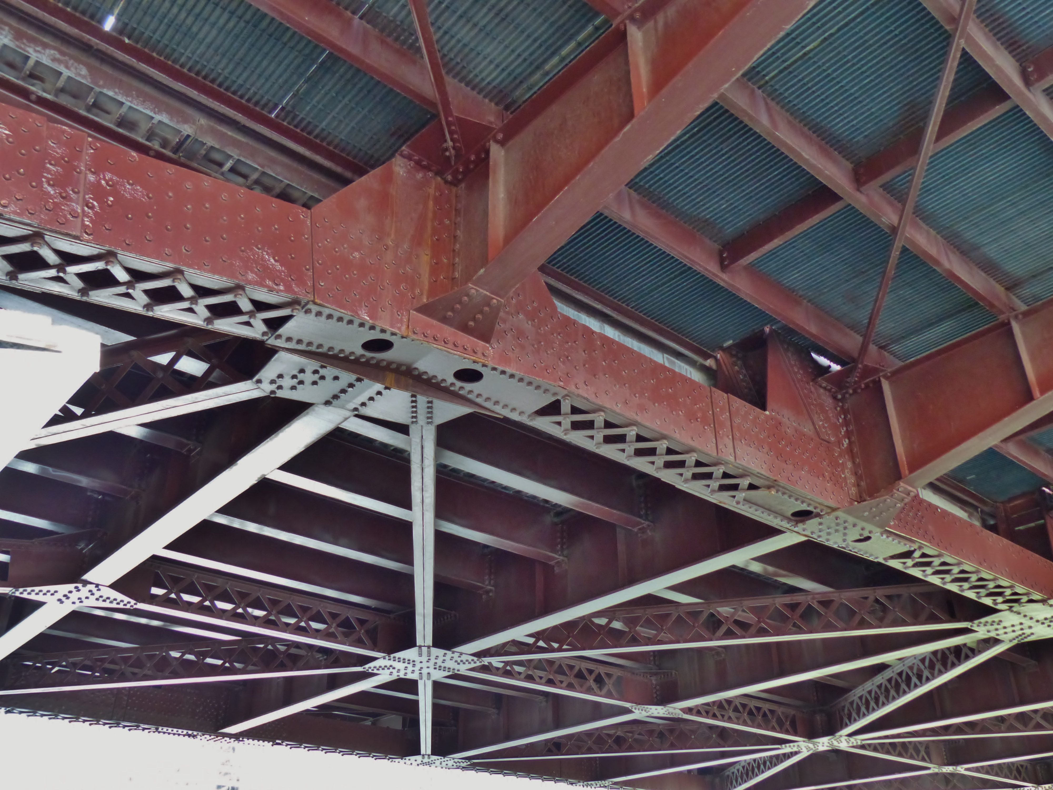
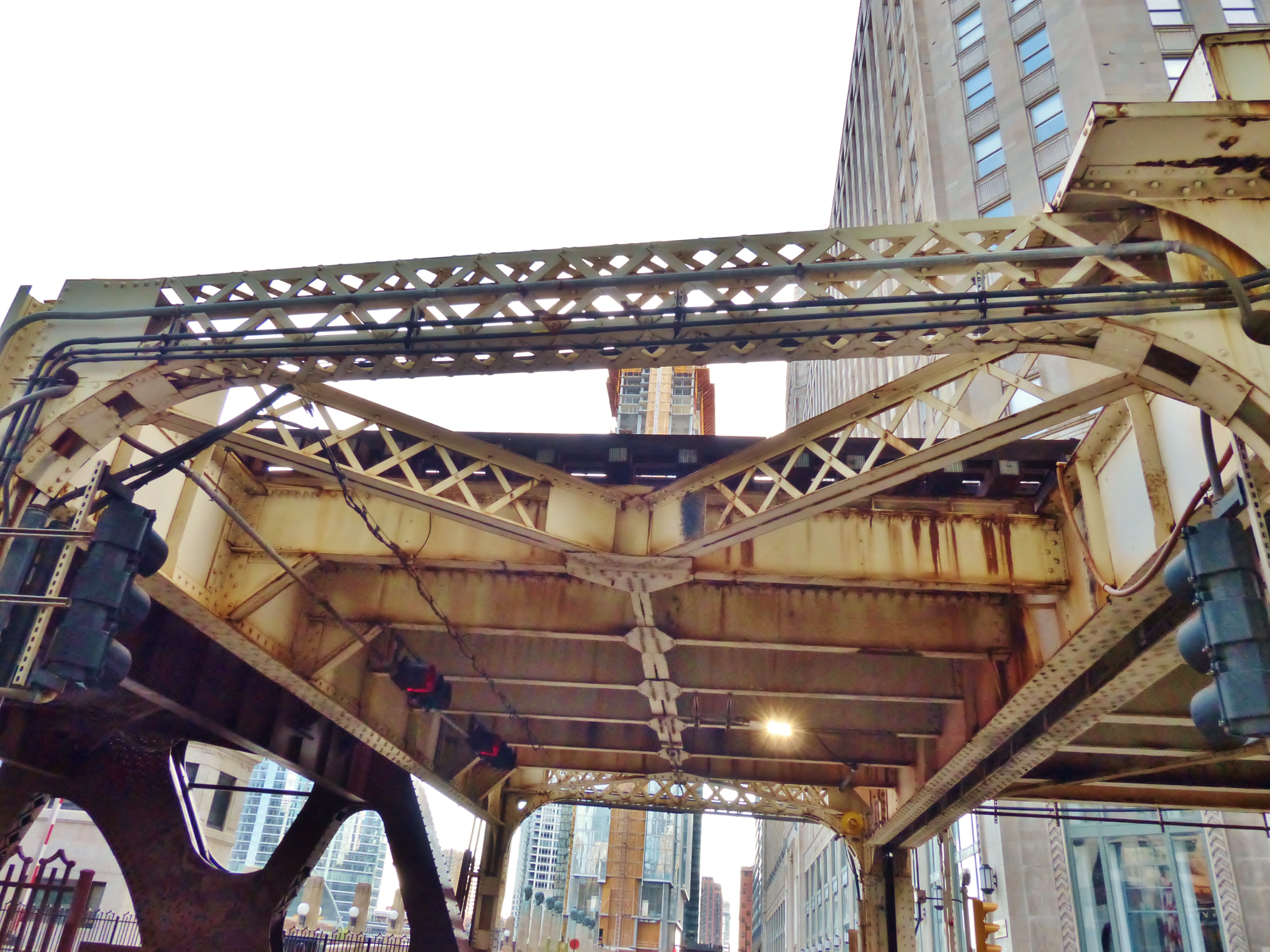
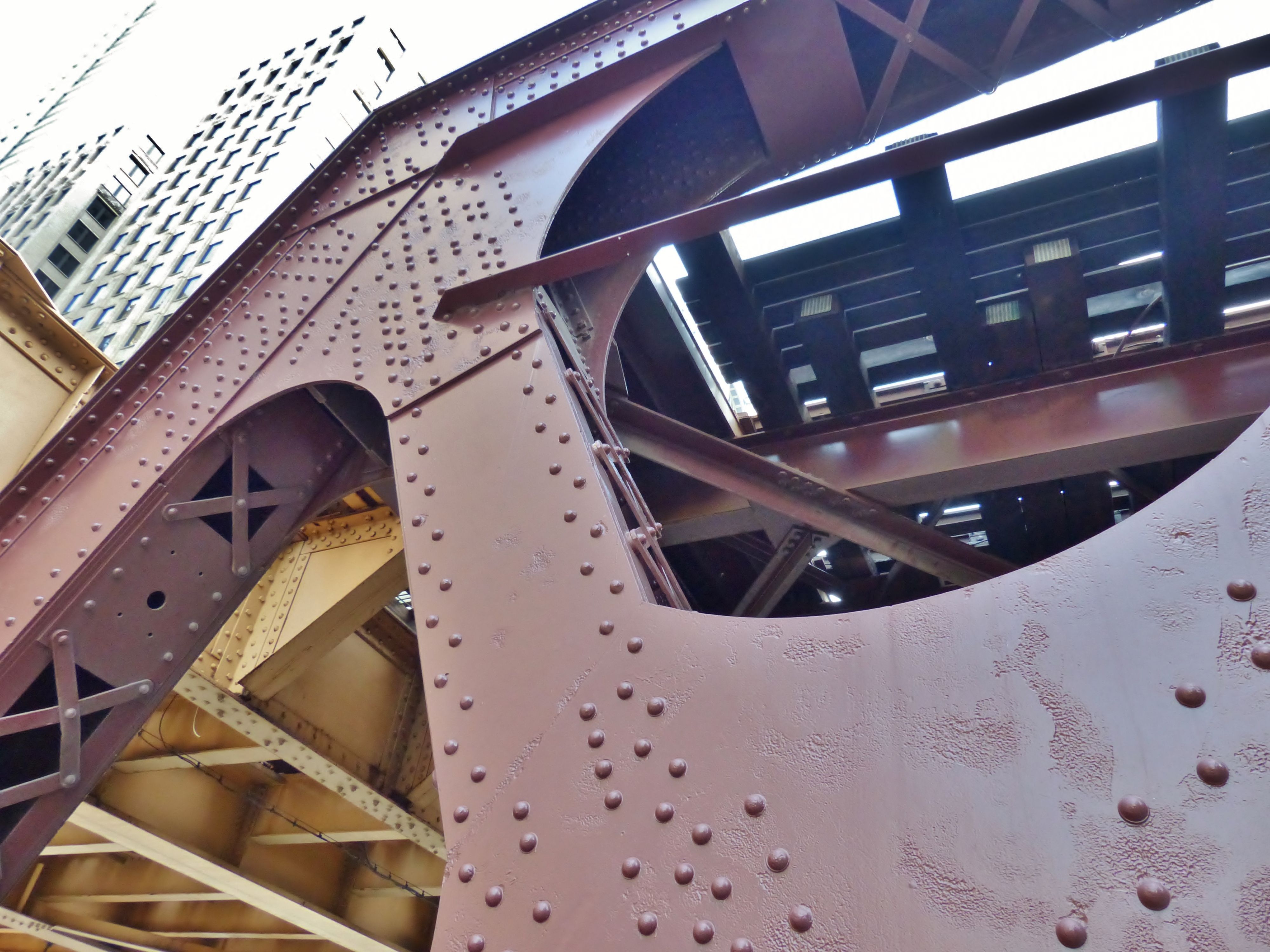
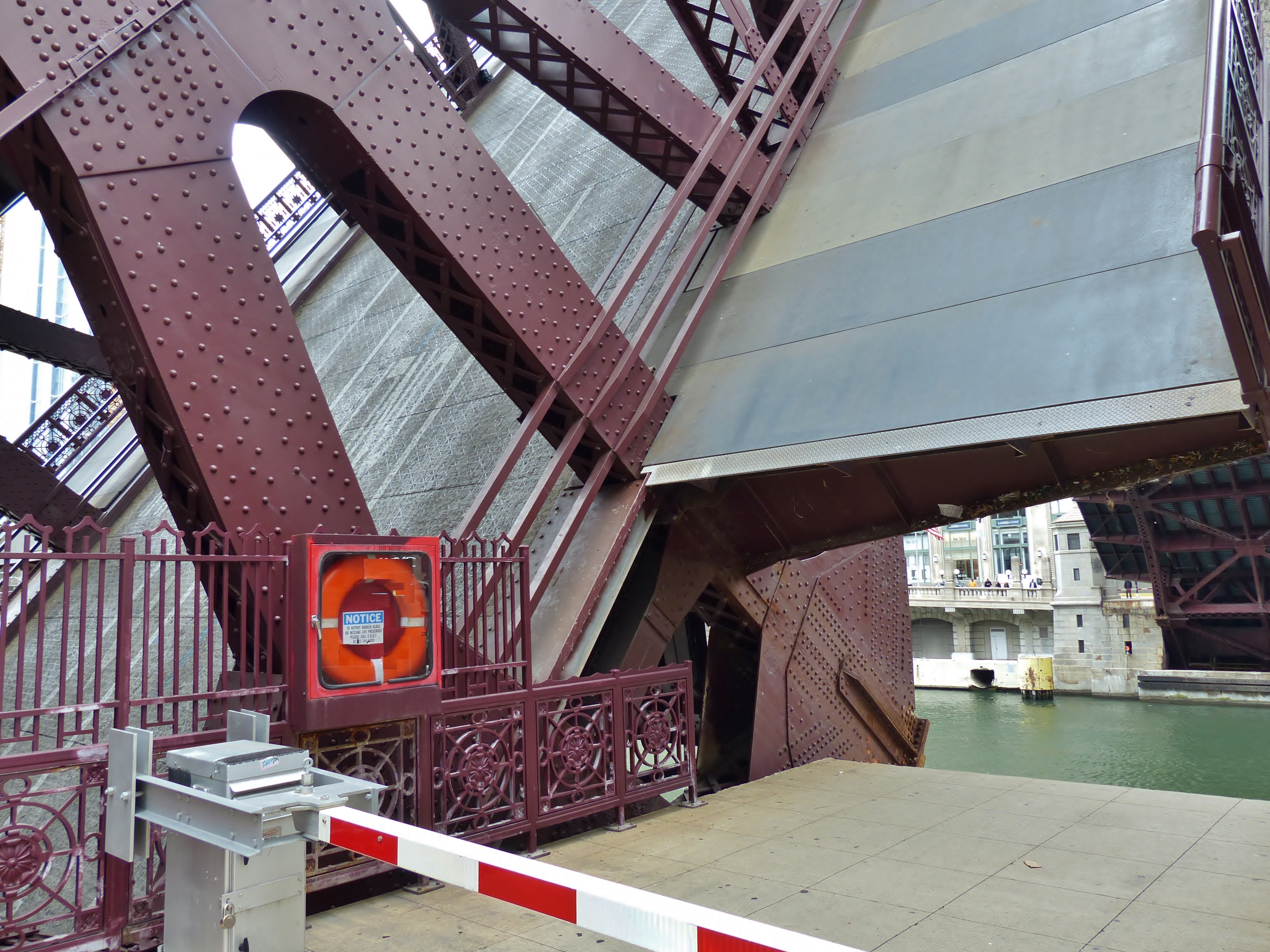
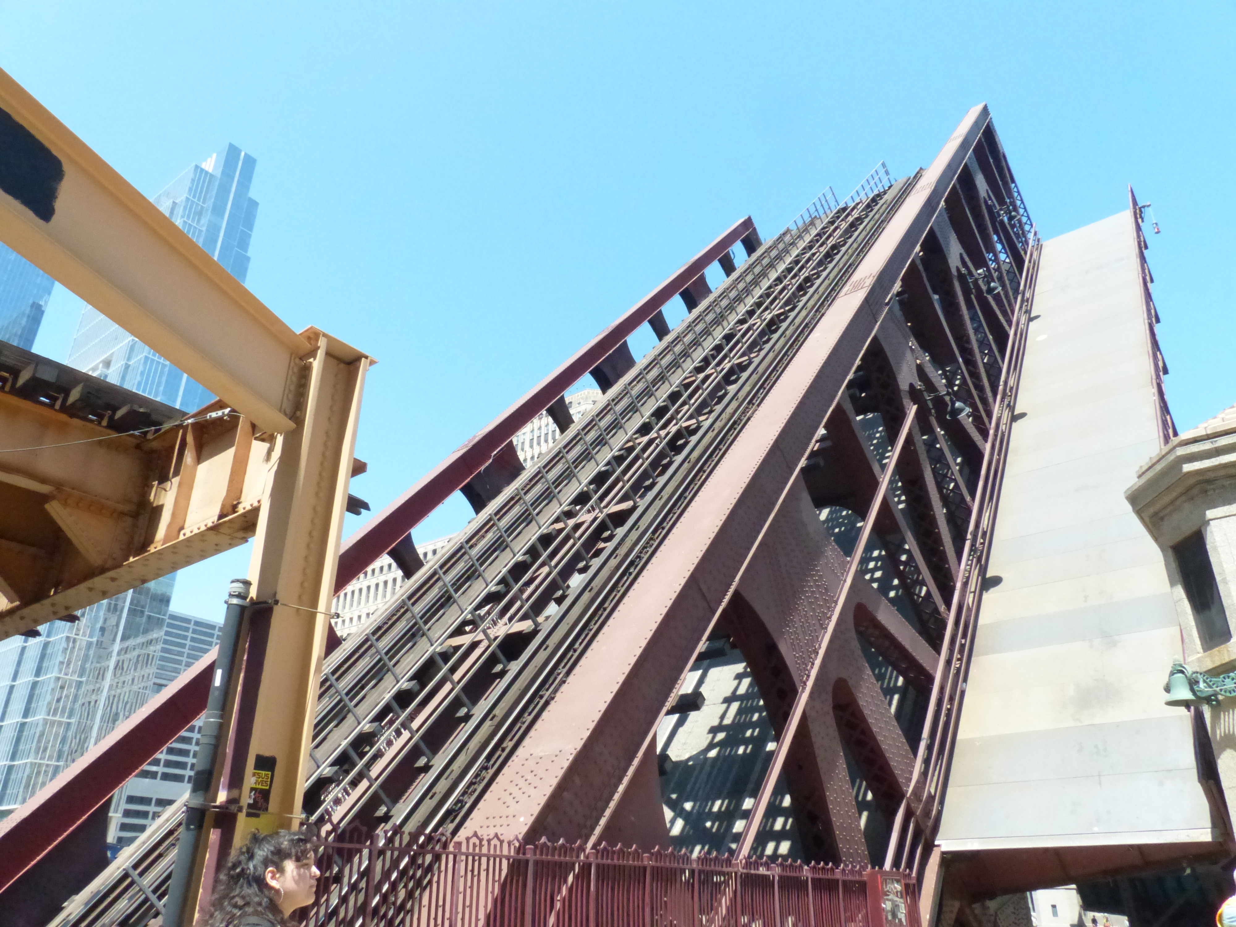
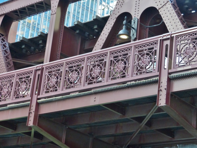
II. Top and bottom chord photographs.
These photographs display critical structural elements of the bridge: gusset plates, rivets, nuts and bolts, X-bracing, lateral bracing, and the road deck.
Through the axis of the bridge during bridge lifts or from sidewalks, bottom chord connections are notable in the parallel bracing and gusset plates at the nodes towards the clear span portion of the superstructure.
II A. Top chord
II B. Bottom chord
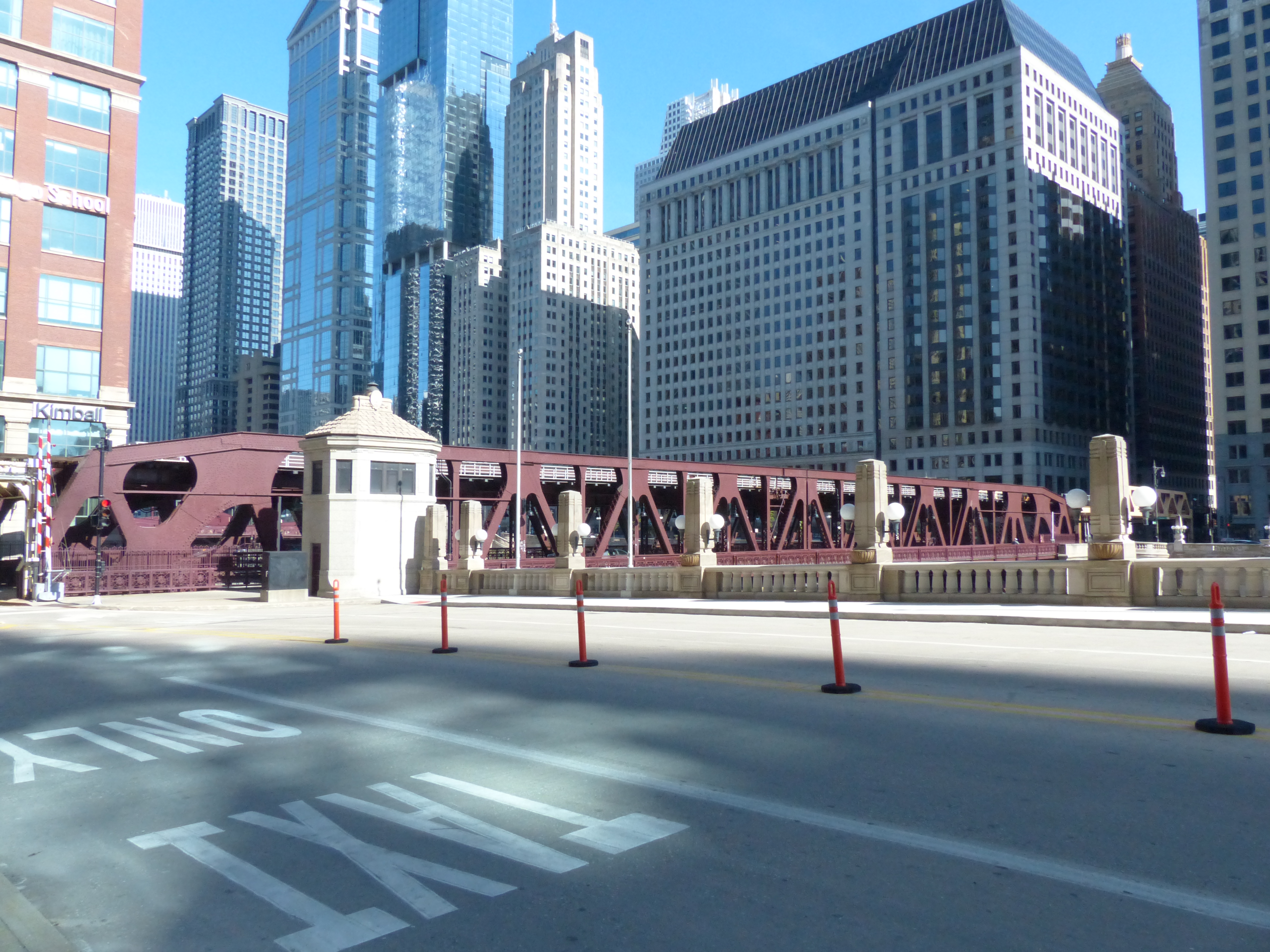
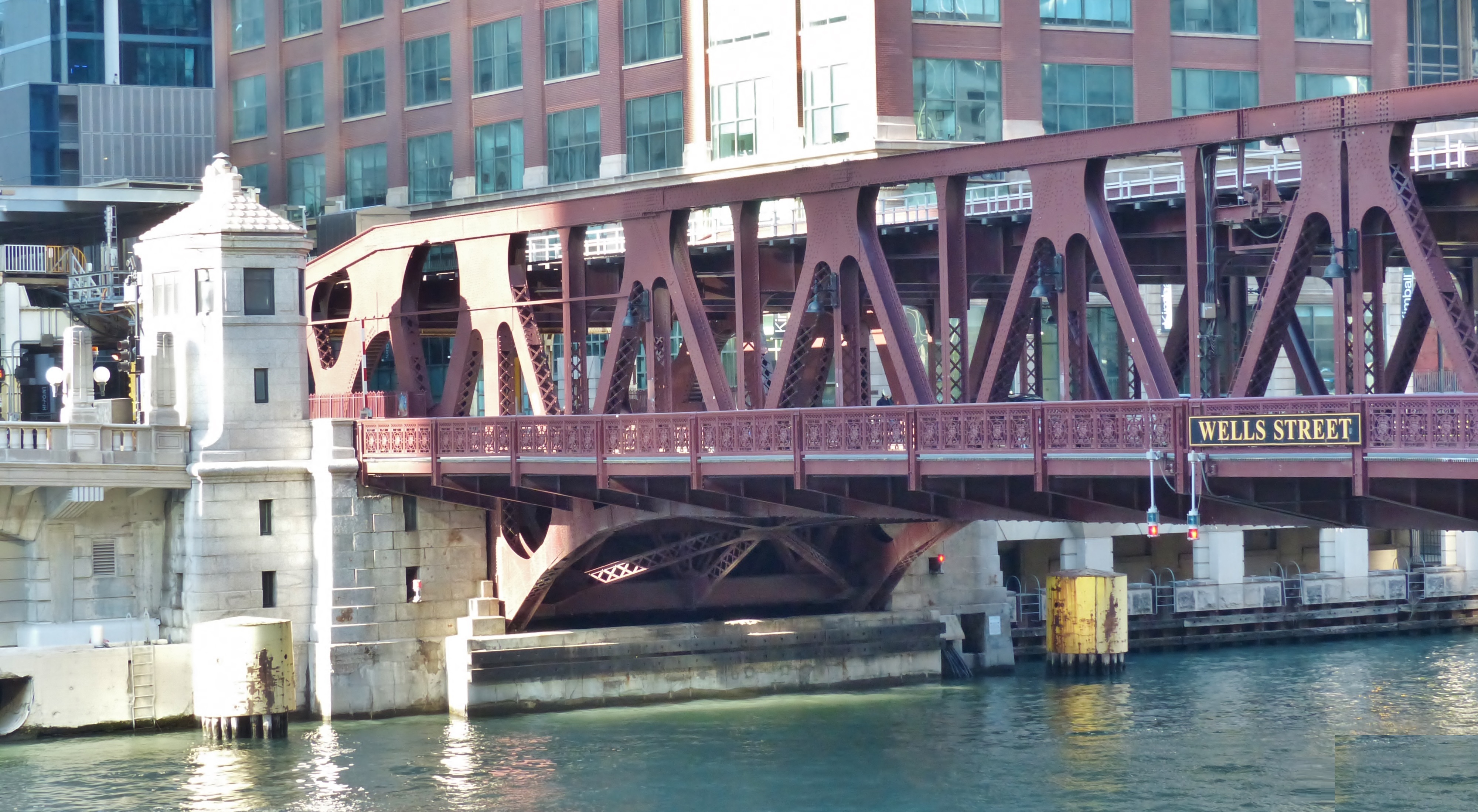
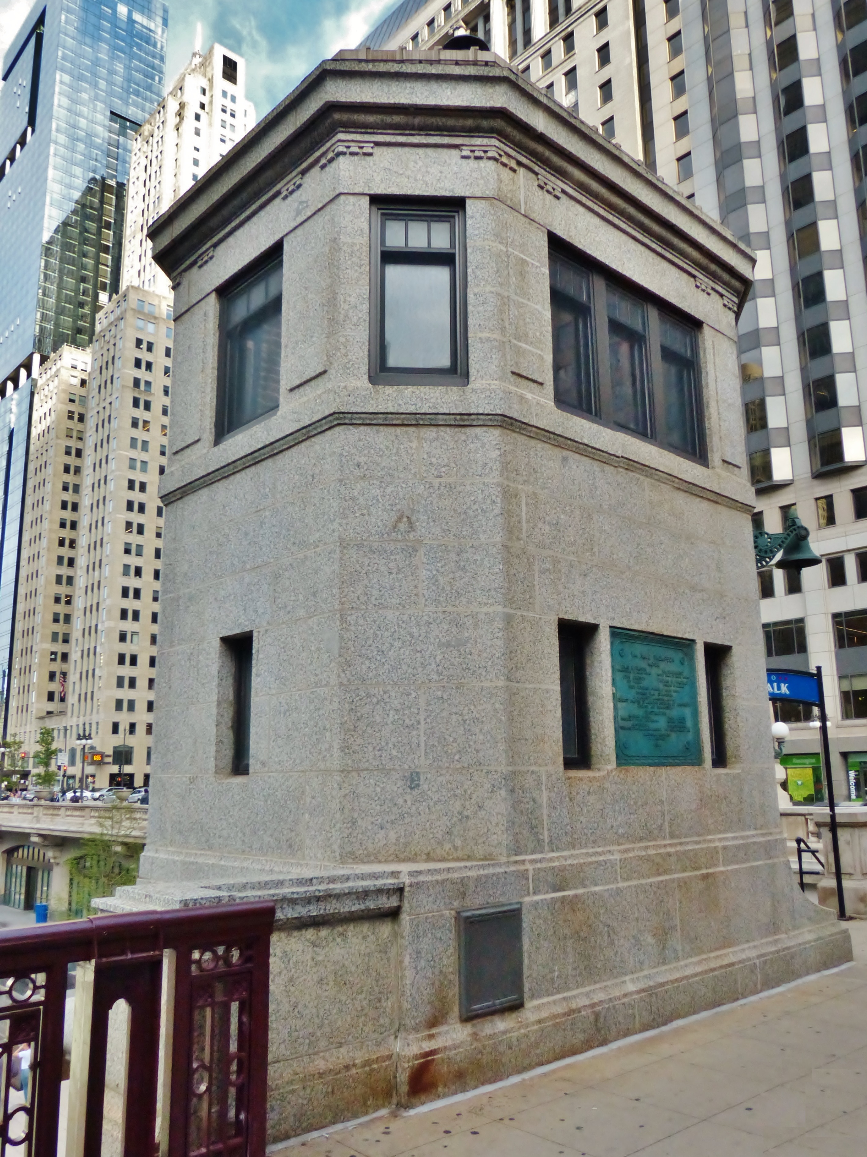
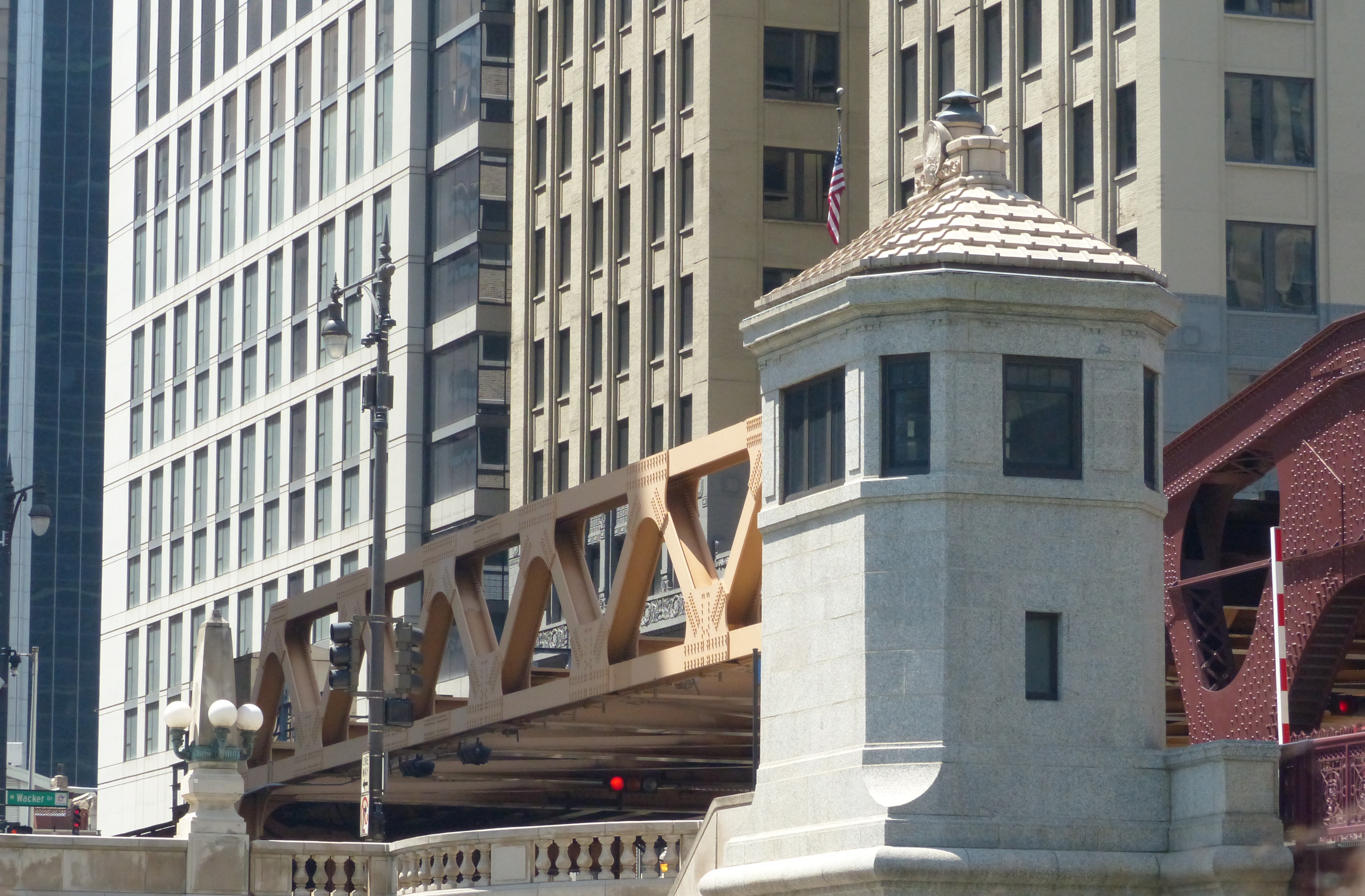
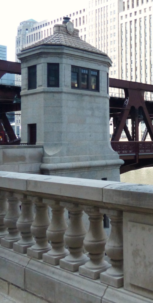
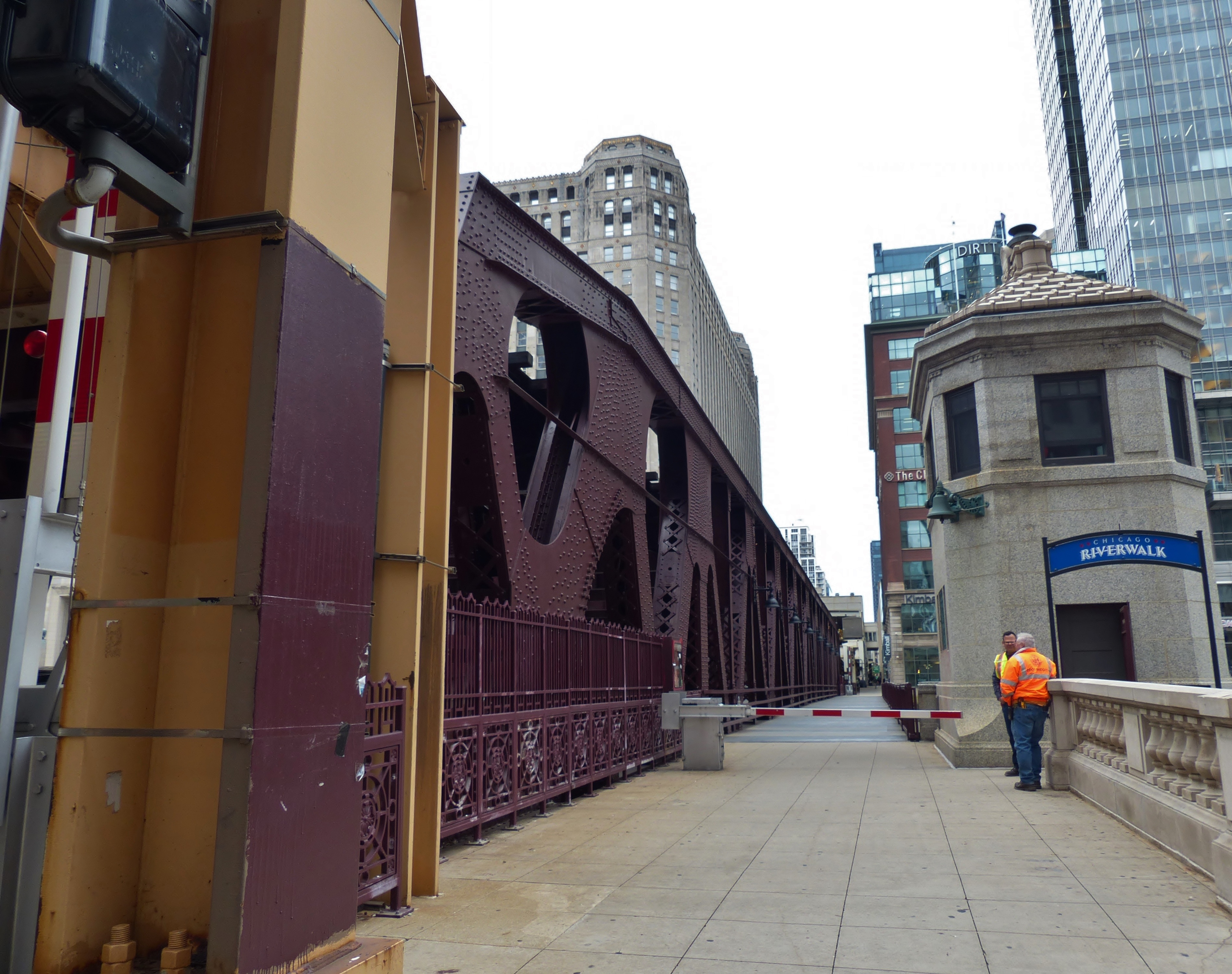
III. Bridge Tender’s Houses
Bridge tender’s houses are part of the rich history of Chicago’s waterway infrastructure. They serve as control centers for operating bascule bridges, housing the equipment and personnel needed to raise and lower the bridge leaves.
These structures are integral to the mechanics and management of movable bridges, especially in cities like Chicago where river traffic intersects with dense urban infrastructure.
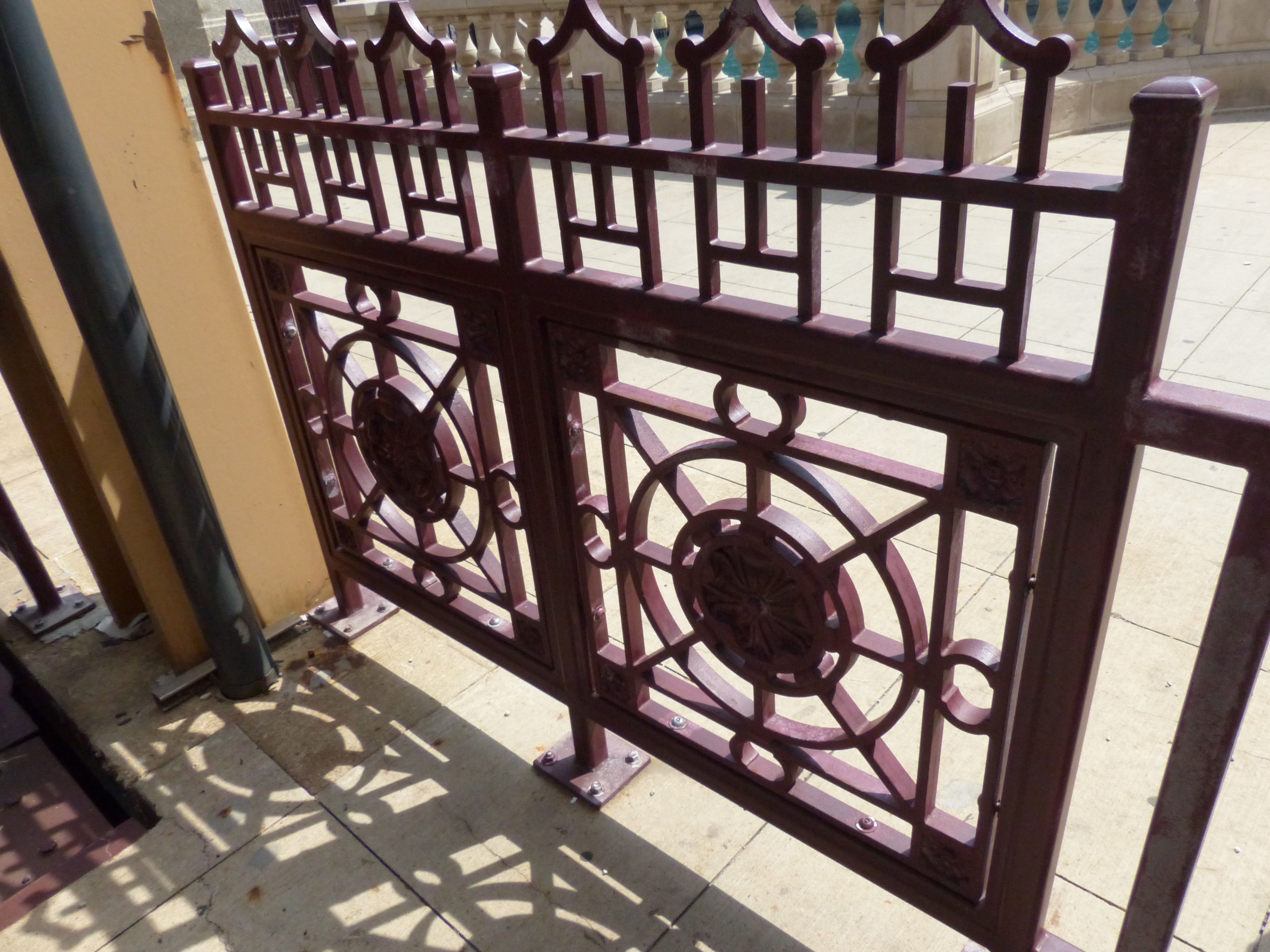
The bridge tender’s houses exhibit a mélange of features of the Art Deco design era plus elements from classical antiquity. Art Deco flourished in the 1920s, a significant period of construction in Chicago. The diverse styles that influenced it had already appeared in the mid-19th century.
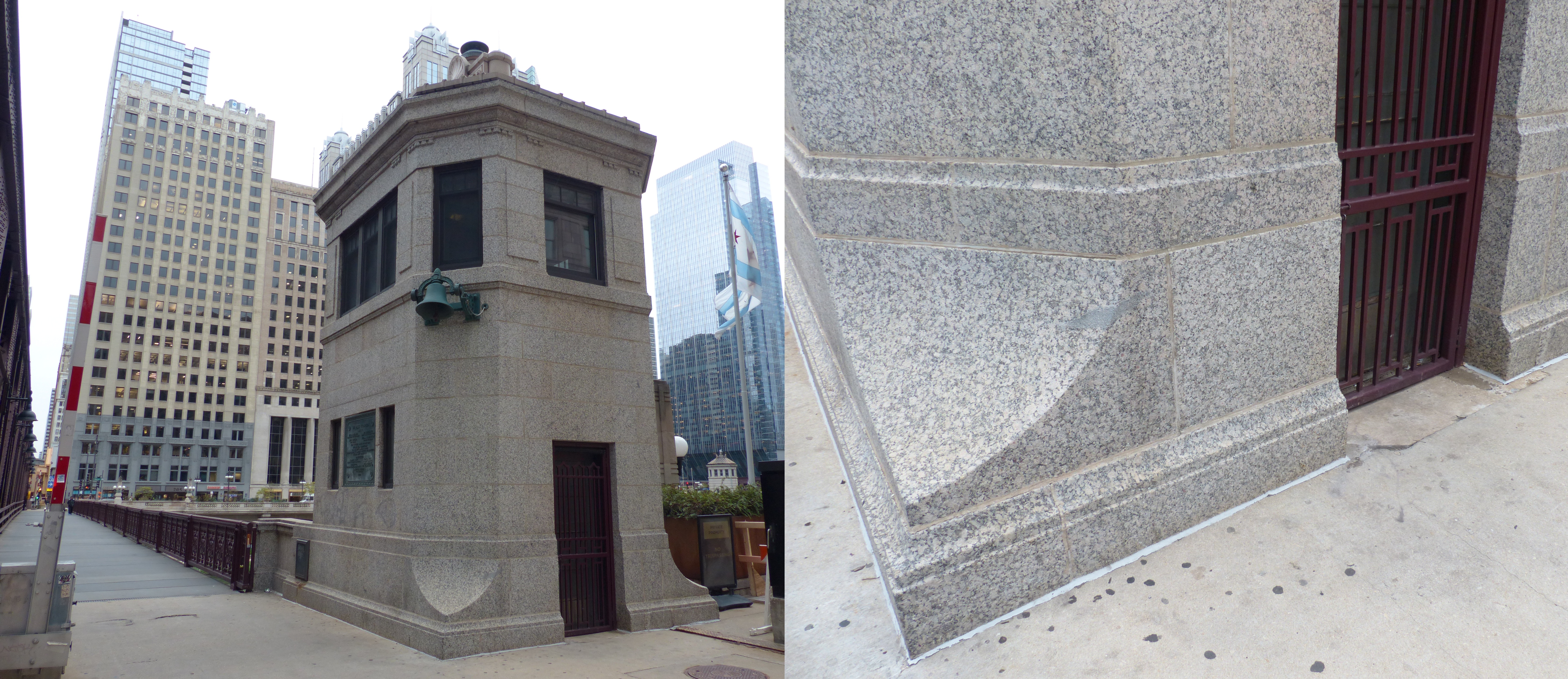
Features of Art Deco on the bridge houses include vertical emphasis, clean lines, simple shapes, elegant simplicity and a streamlined look, and the use of luxurious materials.
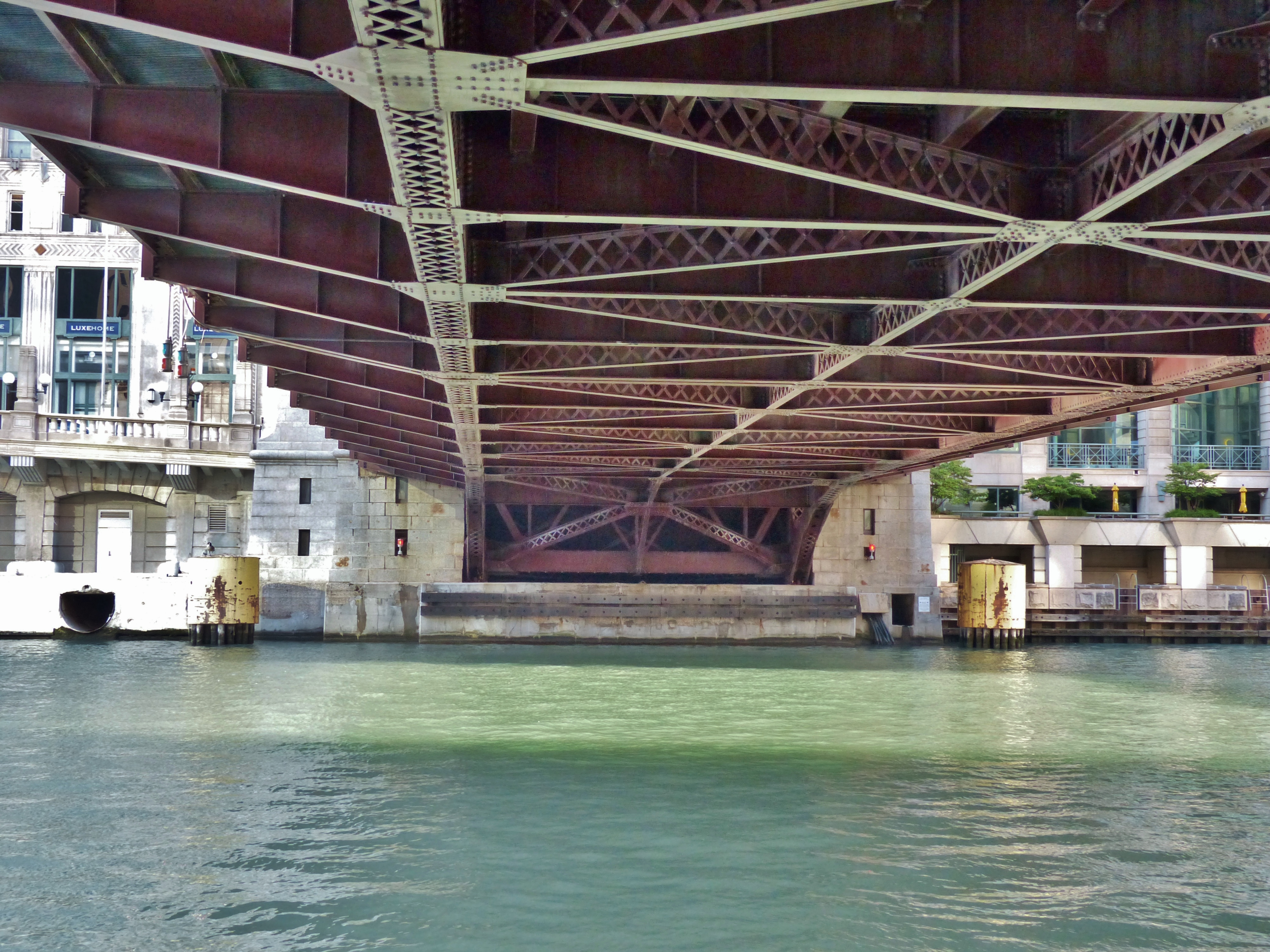
IV. Engineering and Structural Details: Bracing, Plates, and Supports, and Substructure
The substructure of a bascule bridge includes elements like sidewalk cantilevers, stringers, floor beams, bridge pits, and abutments.
- Movable Leaf: On a bascule bridge, stringers are part of the rotating leaf. They must be precisely aligned to avoid interference with the counterweight and trunnion mechanisms.
- Deck Support: Often topped with steel grating or concrete panels, stringers anchor these surfaces securely while allowing for drainage and thermal expansion.
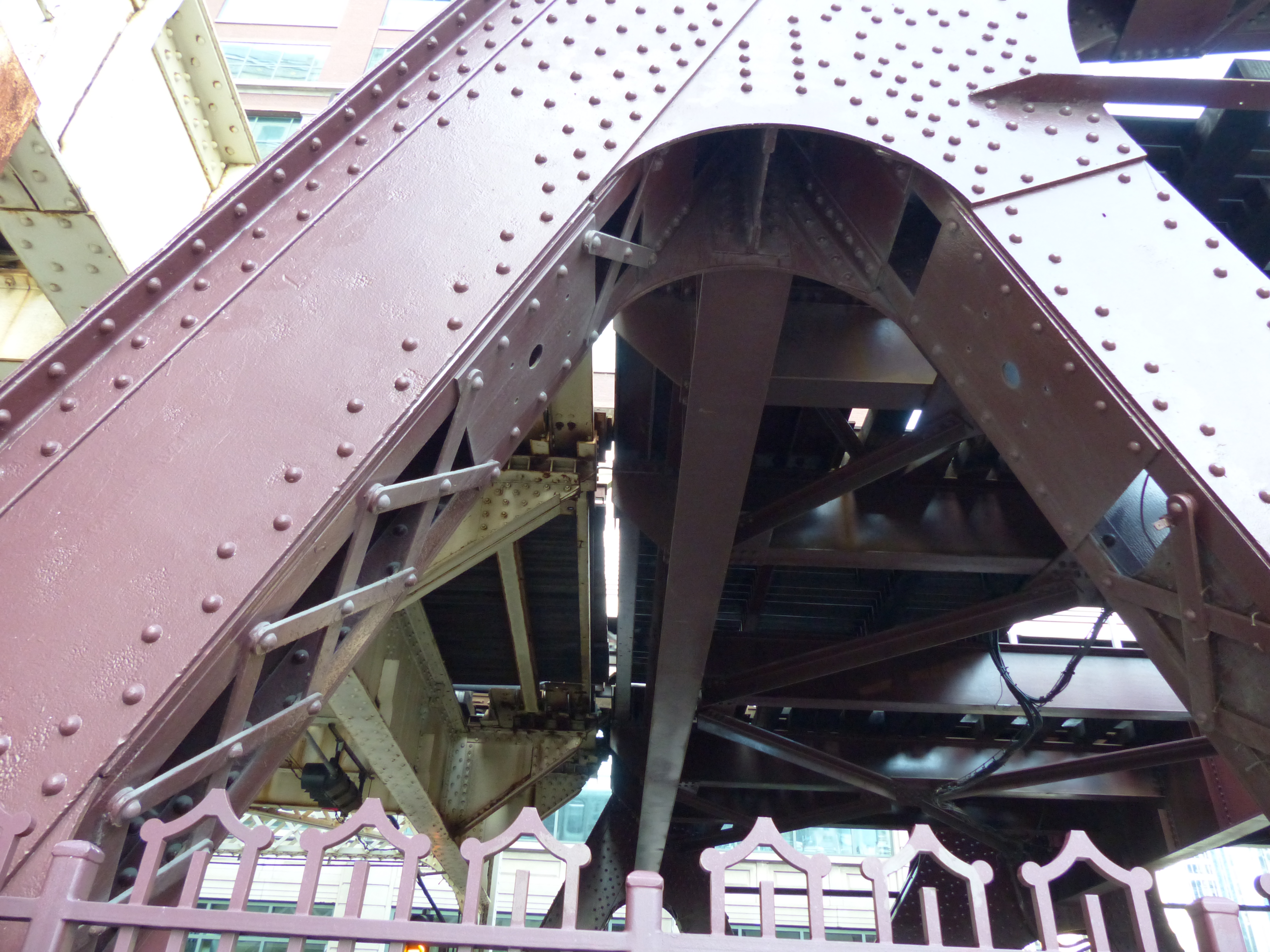
IV A. Intermediate and Lateral Bracing
Intermediate bracing serves several critical structural and operational functions on movable span bridges. They resist torsional and lateral deformation when the leaves are raised, and the trusses are cantilevered and vulnerable to lateral wind loads.
- Intermediate bracing helps maintain geometric alignment between the two leaves, especially critical at the center lock.
- Misalignment can cause locking failures or uneven wear on mechanical components.
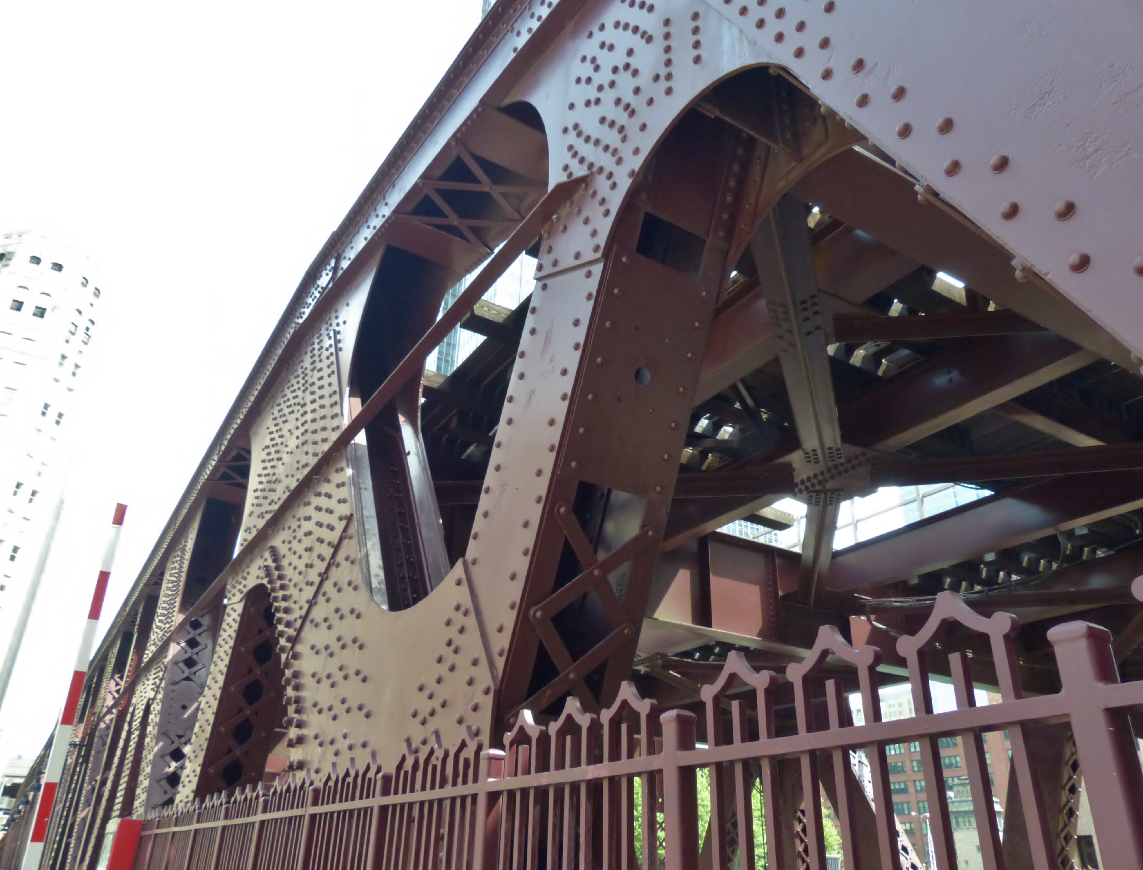
IV B. X-bracing
X-bracing on double-deck bascule bridges like the Wells Street Bridge serves a crucial structural and functional role, especially given the complexity and mass of these movable spans.
Primary functions of X-bracing
- X-bracing resists transverse loads—such as wind, vibration from trains, and dynamic forces during bridge movement.
- On double-deck configurations, the upper deck (CTA trains) and lower deck (vehicular/pedestrian traffic) introduce differential loading, making lateral reinforcement essential.
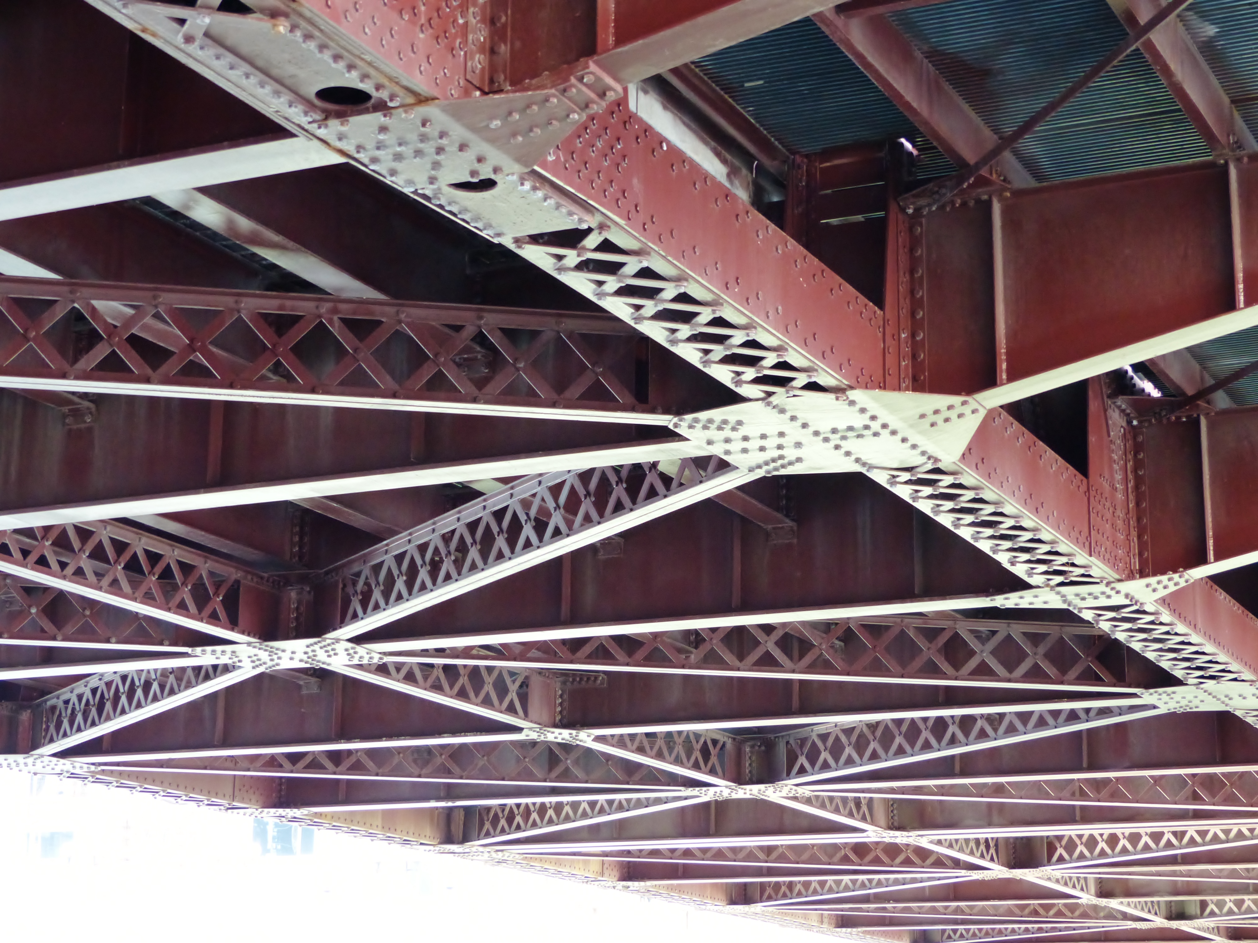
The crisscross pattern helps distribute vertical and horizontal loads across the truss system. It reduces stress concentrations at joints and riveted connections, especially near the trunnion bearings and counterweight housings.
Functions for Torsional Rigidity
- Double-deck bascule bridges are susceptible to torsional forces due to asymmetrical live loads (e.g., a train on one side, cars on the other)
The X-bracing is especially prominent in the vertical truss panels and portal frames, reinforcing the bridge against the dynamic loads of elevated rail traffic and frequent leaf operation.
- This is especially useful in shorter or less heavily loaded members, where full lacing would be excessive or visually disruptive.
- They reduce the risk of stress concentrations at rivet points or junctions, especially near gusset plates and panel points.
During leaf rotation, the bridge experiences non-uniform stress across its span. X-bracing stabilizes the structure while the leaves pivot, especially in the approach spans and fixed trunnion zones.
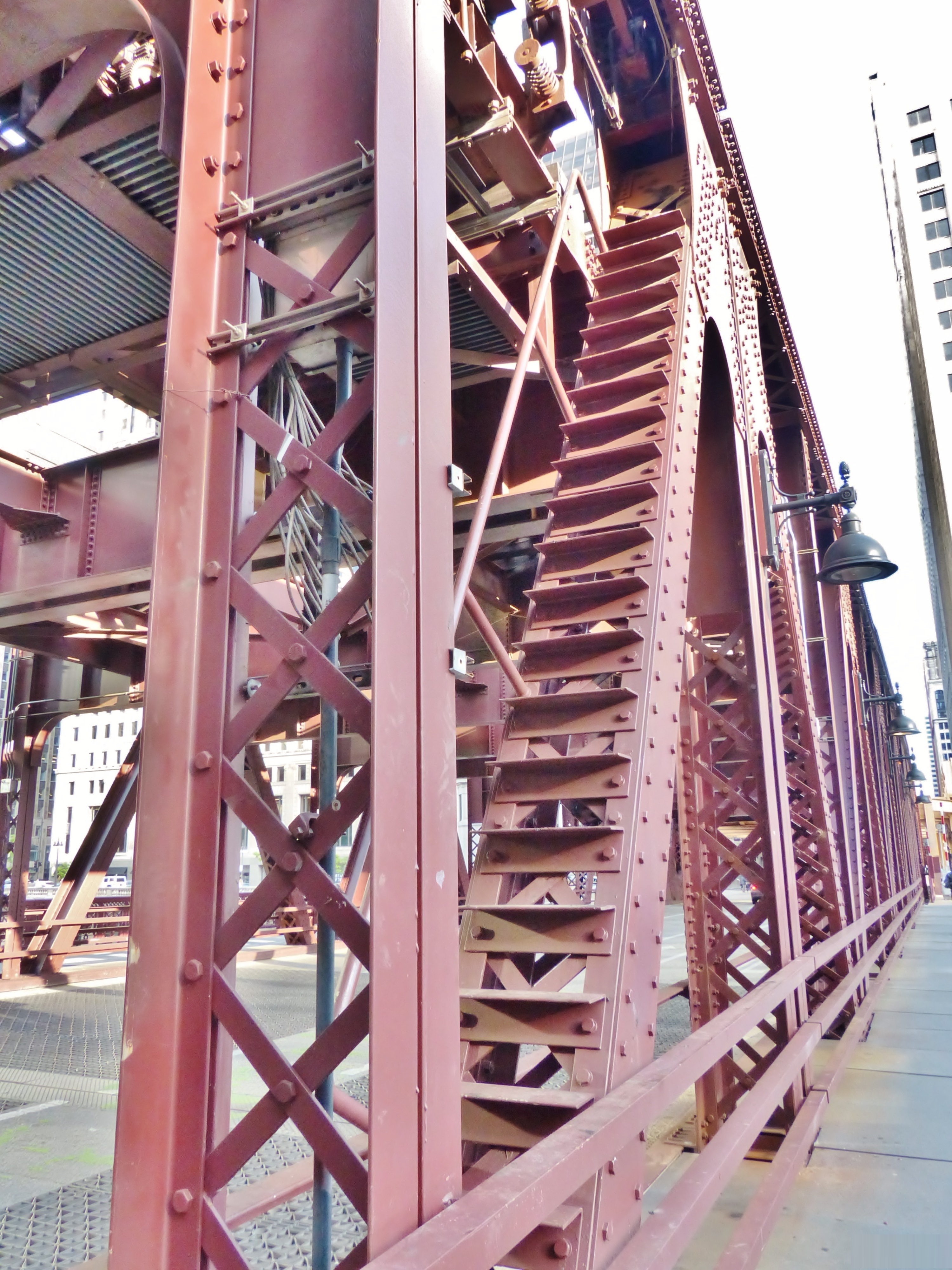
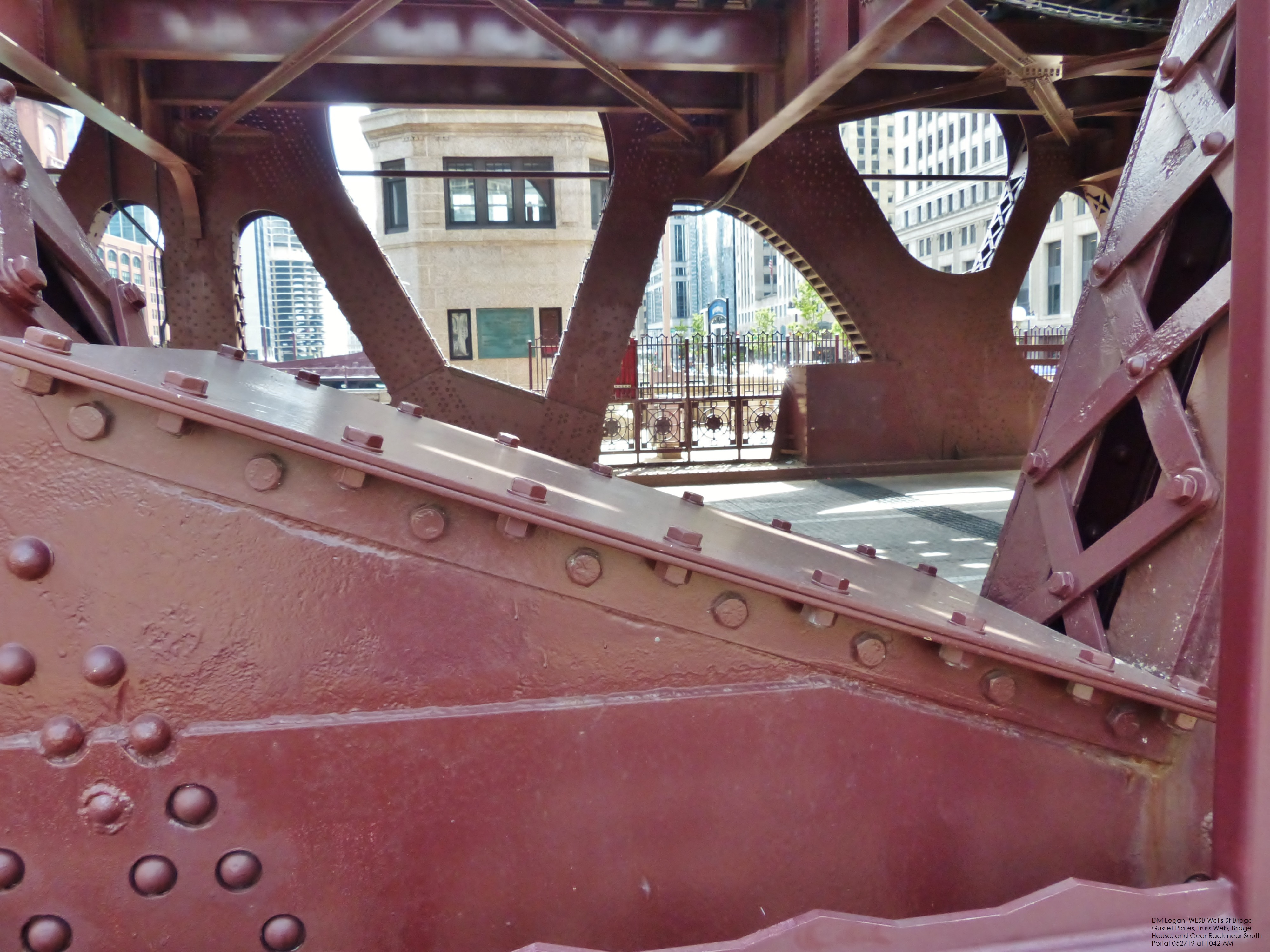
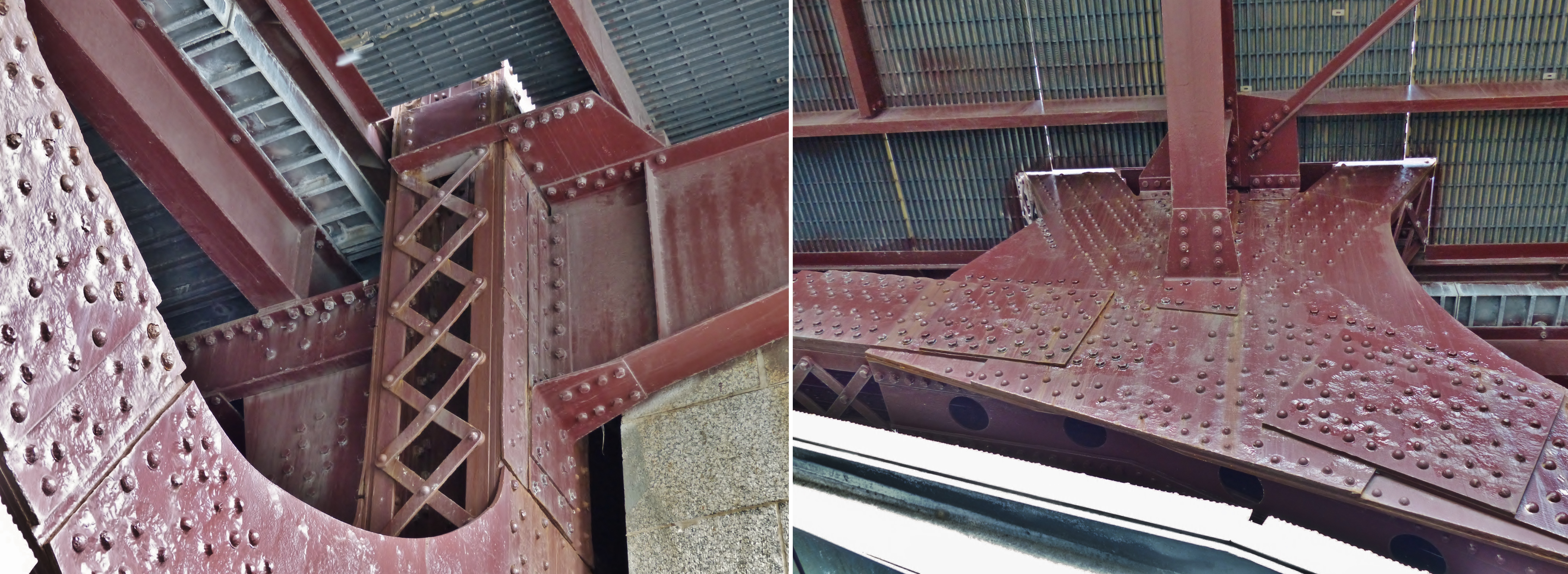
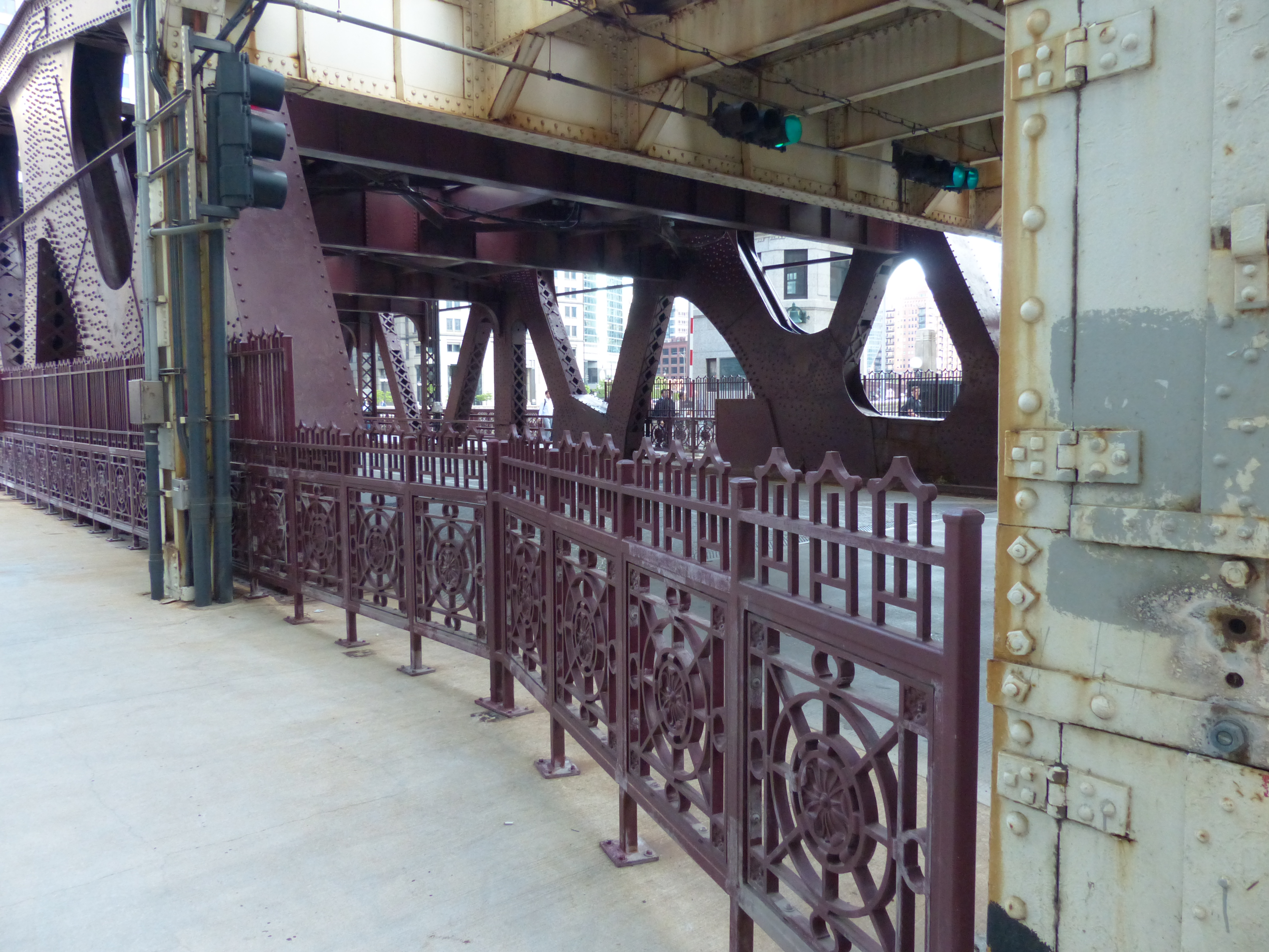
IV C. Batten Plates and Gusset Plates
The word “batten” may be familiar in the phrase “batten down the hatches.” Its origins are from the use of strips of wood or bars nailed across parallel boards to hold them in place. There is the nautical sense of using strips of wood and tarpaulins over a ship’s hatches to prevent leakage in stormy weather.
Gussets were parts of suits of armor in the area of the arms. In a sense of use on a steel bridge, the idea of holding metal pieces together is logical. Gusset plates on a bascule bridge join the truss elements together at key junctions. These precision – engineered plates resist dynamic loads during bridge lifting and lowering.
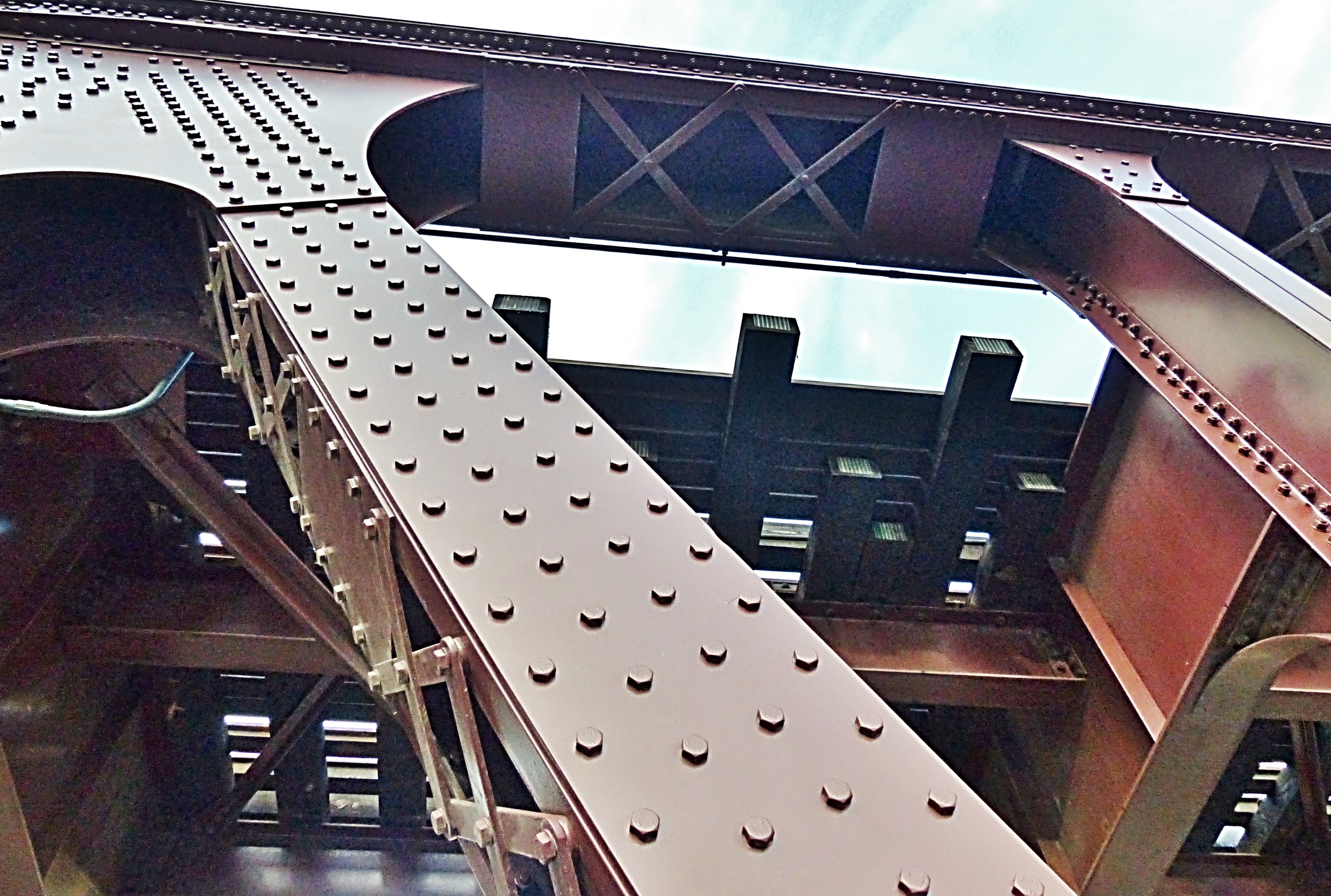
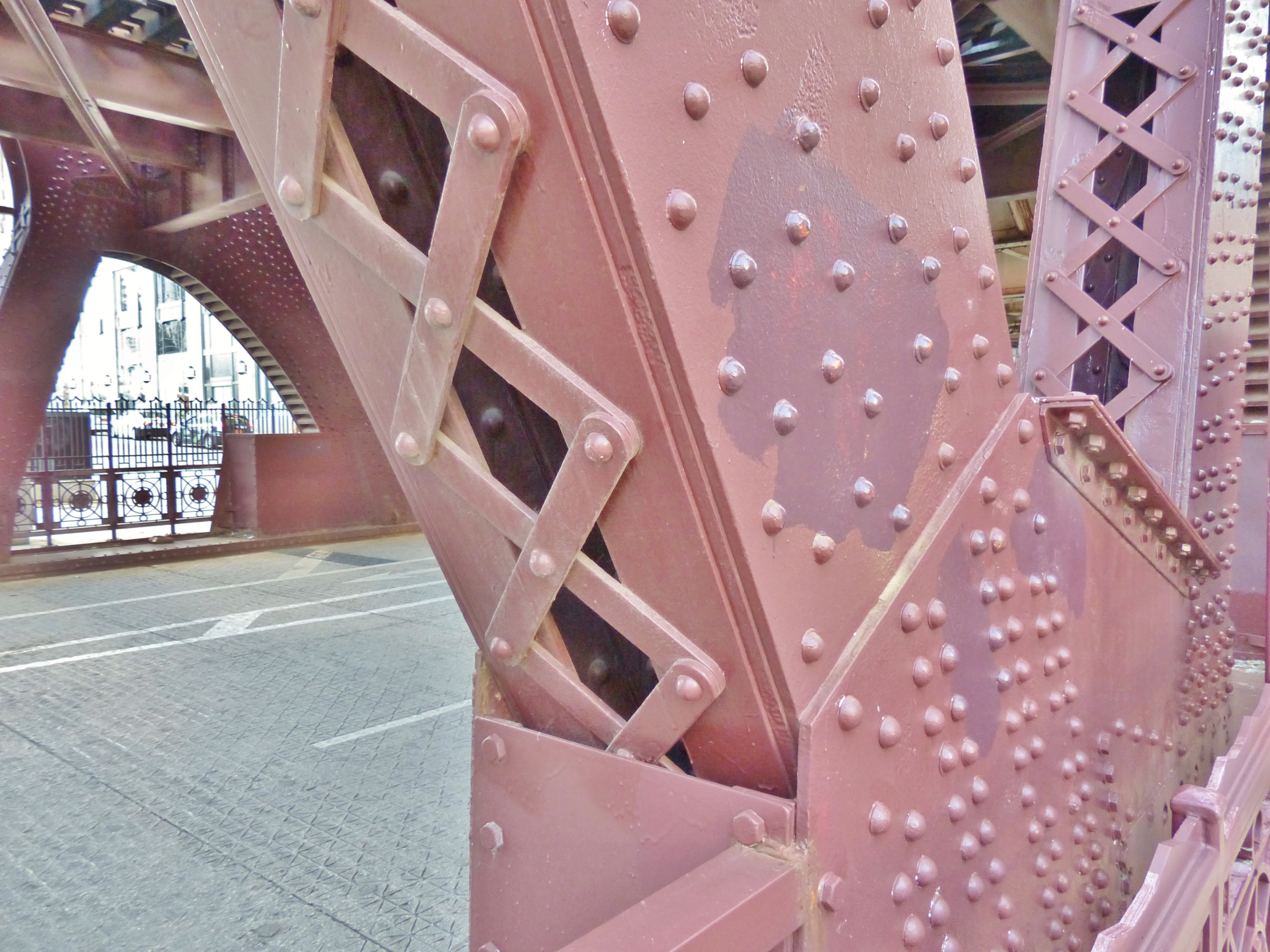
Batten plates on the Wells Street Bridge—and similar riveted truss structures—play a subtle but essential role in maintaining the integrity of built-up members. They are used to tie together individual elements (typically angles or channels) that form a built-up compression member.
On the Wells Street Bridge, these are often seen in vertical and diagonal members of the truss, where multiple steel shapes are riveted side-by-side. The plates prevent buckling or lateral displacement of these elements under compressive loads.

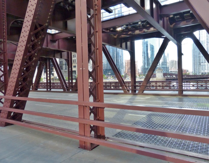
IV D. Road Deck Structures, Floor Beams, Stringers, and Cantilevers
Stringers are longitudinal beams that run parallel to the direction of traffic. They sit between the main girders and support the deck, transferring loads from the deck to the floor system and ultimately to the substructure.
- Load Distribution: Stringers carry live loads (vehicles, pedestrians) and distribute them to floor beams and girders.
- Flexibility: Their slenderness allows for slight flexing, which helps accommodate dynamic loads during leaf movement.
- Spacing: Typically spaced 3–6 feet apart, depending on deck material and traffic demands.
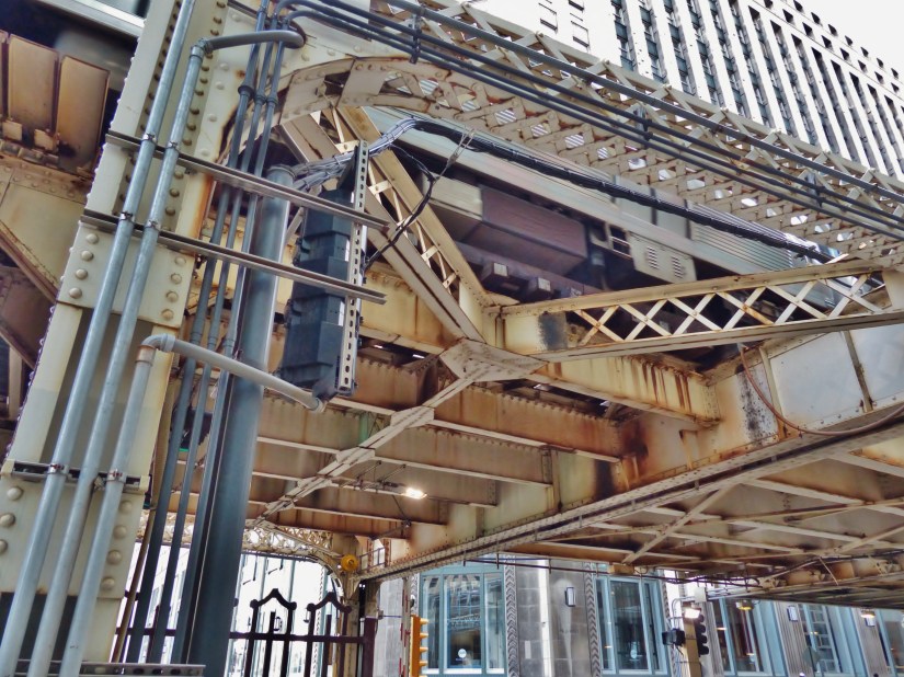
IV E. North Train Deck Approach Span Engineering Features
These sections of the north train deck approach span that link the Brown Line station at the Merchandise Mart to the clear span’s train deck are particularly technically complex.
While primarily functional, batten plates contribute to the visual rhythm of the bridge’s steel work, anchoring the geometry of the truss with regular intervals. Their presence reinforces the bridge’s identity as a machine aesthetic civic structure, where form follows function but also narrates Chicago’s industrial legacy.

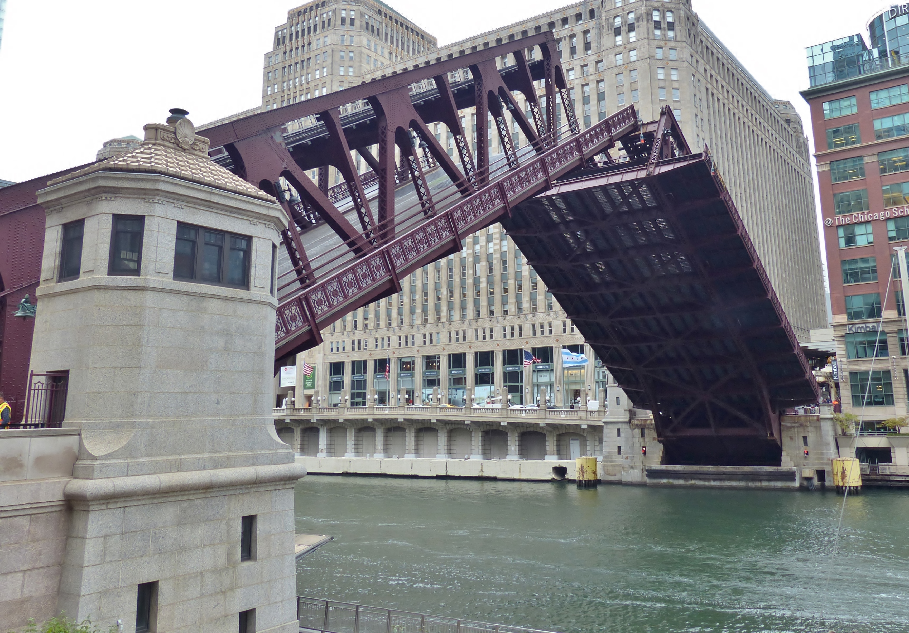
V. Bridge Lifts: Geometry and Civil Engineering in Motion.
- Movable bridges experience dynamic loads during opening/closing.
- Bracing mitigates oscillations and harmonic vibrations, particularly in long-span or heavily trafficked structures.
VI. Civic Symbolism and Decorative Details
Conclusion
Chicago’s history of the use of movable bridges (swing, rolling lift, vertical lift, and trunnion styles) began from around the founding of the town in 1834. The lay of the Chicago River’s narrow depths to around 21 feet with some deeper pockets, and winding widths along its branches, of around 125 to over 200 feet made bridge engineering a true civic challenge.
The building of the classic trunnion bascule bridges as we view them today began around 1900, as the city’s population reached 1 million. The trunnion bascule design allowed for the large axles (the trunnions) and the massive counterweights that balance the bridge leaves to be hidden in the riverbank.
Changes in the river’s course, dredging, and advances in engineering help maintain the river as a vital waterway for shipping and industry. Wells Street Bridge is an essential link for daily commuters.
The city’s collection of bascule bridges is one of the best in the world, and with sensitive maintenance such as that being done on spans along all the river’s branches, these spans will continue to serve travelers and commerce for decades to come.
Resources
- Wikipedia contributors. “Wells Street Bridge (Chicago).” Wikipedia, The Free Encyclopedia. Wikipedia, The Free Encyclopedia, 27 May. 2025. Web. 4 Oct. 2025.
- Copilot. “Response to query of Substructure of a bascule bridge.” Microsoft, 2025. https://copilot.microsoft.com/shares/b2ZZBeMu7ZUDVR4HT9iui. https://copilot.microsoft.com/chats/SpMhWR25D684bzLHt92ZY.
- Copilot. “Response to query of stringers on a bascule bridge.” Microsoft, 2025. https://copilot.microsoft.com/shares/QZpkFfG6KwbQcEwpYETqo. https://copilot.microsoft.com/chats/SpMhWR25D684bzLHt92ZY.
- Copilot. “Response to query of What is the purpose of intermediate bracing on a double leaf, double deck bascule bridge?” Microsoft, 2025.
- Copilot. “Response to query of What kind of bracing is this curved element above the road deck on Chicago’s Wells Street Bridge?” Microsoft, 2025.
- Copilot. “Response to query of Chords on a bascule bridge.” Microsoft, 2025. https://copilot.microsoft.com/shares/bJHdtTZ1PY3KmQhUw5XA5.
- Copilot. “Response to query of What is the function of X-bracing on a double-deck bascule bridge like Lake Street Bridge in Chicago?” Microsoft, 2025.
- Copilot. “Response to query of What is the function of batten plates on the Wells Street Bridge in Chicago?” Microsoft, 2025.
- Harper, Douglas. “Etymology of gusset.” Online Etymology Dictionary, https://www.etymonline.com/word/gusset. Accessed 6 October, 2025.
- Harper, Douglas. “Etymology of batten.” Online Etymology Dictionary, https://www.etymonline.com/word/batten. Accessed 6 October, 2025.
- “batten.” Wiktionary. 7 Sep 2025, 20:17 UTC. <https://en.wiktionary.org/w/index.php?title=batten&oldid=86678896> 6 Oct 2025, 20:03.
- Copilot. “Response to query of What is the function of gusset plates on Chicago’s Wells Street Bridge?” Microsoft, 2025.
- Copilot. “Response to query of What made bascule bridges essential in Chicago’s infrastructure?” Microsoft, 2025. https://copilot.microsoft.com/shares/kqxpUMV8Nh6VJNVT8DoYD.
- Copilot. “Response to query of How wide and how deep is the Chicago River along its Main Branch and South Branch?” Microsoft, 2025. https://copilot.microsoft.com/shares/nHkZ4kF12yzGPoWTRQkxb.
- Wikipedia contributors. “Bascule bridge.” Wikipedia, The Free Encyclopedia. Wikipedia, The Free Encyclopedia, 17 Jun. 2025. Web. 7 Oct. 2025.
- Copilot. “Response to query of What is a node on a bascule bridge.” Microsoft, 2025. https://copilot.microsoft.com/shares/aeMUUv9DkWKD2o3YN6bD8.
- Copilot. “Response to query of What are the bridge tender’s houses for Chicago’s Wells Street Bridge built of?” Microsoft, 2025.
- The Editors of Encyclopaedia Britannica. “Art Deco”. Encyclopedia Britannica, 3 Sep. 2025, https://www.britannica.com/art/Art-Deco. Accessed 8 October 2025.
- Wikipedia contributors. “Art Deco.” Wikipedia, The Free Encyclopedia. Wikipedia, The Free Encyclopedia, 1 Oct. 2025. Web. 8 Oct. 2025.
- Copilot. “Response to query of What is the function of bridge tender’s houses along bascule bridges?” Microsoft, 2025. https://copilot.microsoft.com/shares/tpS7eF6WVCaBrnHvvyERY.
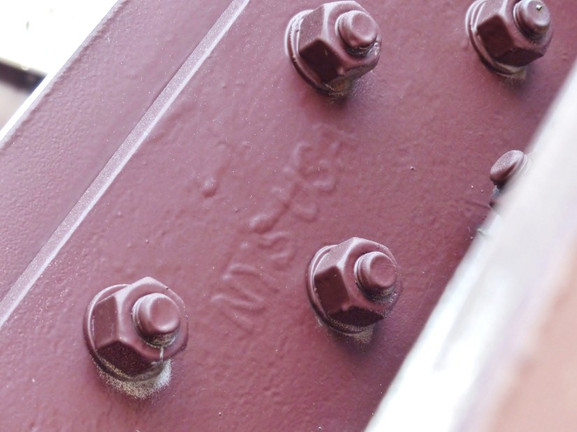
- Copilot. “Response to query of What role did NYS Nucor Yamato Steel have in the rebuilding of Chicago’s Wells Street Bridge?” Microsoft, 2025.
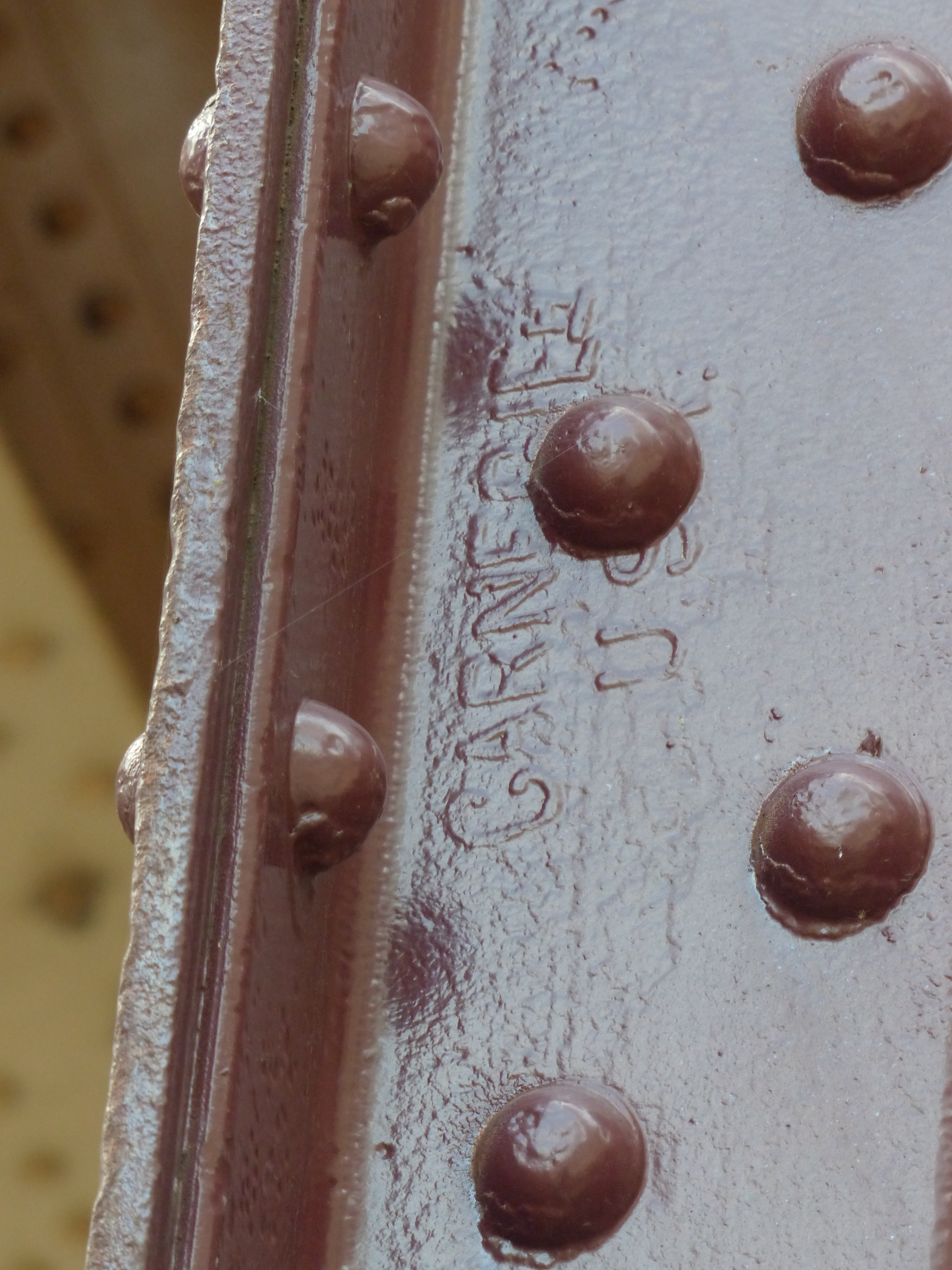
- Copilot. “Response to query of What role did Carnegie USA Steel have in the construction or rebuilding of Chicago’s Wells Street Bridge?” Microsoft, 2025.
